No just located
Most of the weight work is done by the ball joints in the top and bottom control arms
If you were handy with the tools it would be possible to fit 2wd front cv complete with abs tone ring from a 2 wd challenger for driving around the city and for low range 2wd, and install the full cv's when going out 4x4ing
Not much additional effort really if you already change out rims and tyres, maybe 1 hour total both sides
Now from previous discussions you will need to install a blank into the diff and the bearing/ hub as the diff will leak, and the bearings will fail very quickly without a shaft to press down upon
Low range 2wd
Low range 2wd
![]() by 4wd26 on Tue Jun 24, 2014 6:14 pm
by 4wd26 on Tue Jun 24, 2014 6:14 pm
-
4wd26 - Moderator
- Posts: 8299
- Joined: Tue Dec 18, 2007 3:00 pm
- Location: Bayside Bundy and Monto
Re: Low range 2wd
![]() by biggibbo on Tue Jun 24, 2014 6:46 pm
by biggibbo on Tue Jun 24, 2014 6:46 pm
Where's Lee? Surely he must have pulled one apart by now 
-

biggibbo - Posts: 2165
- Joined: Mon Jun 07, 2010 9:20 am
- Location: Newcastle. NSW
Re: Low range 2wd
![]() by Lunny on Tue Jun 24, 2014 6:53 pm
by Lunny on Tue Jun 24, 2014 6:53 pm
As he says...... He pays people to do that lol....
Lunny
-
Lunny - Posts: 1708
- Joined: Mon Mar 11, 2013 5:39 pm
- Location: North Brisbane, QLD
Re: Low range 2wd
![]() by a9x_hatch on Fri Jun 27, 2014 6:38 pm
by a9x_hatch on Fri Jun 27, 2014 6:38 pm
har05l wrote:A9x, you could always by a ML and perform the trickery and have 2 tritons sitting in the driveway, his and hers.
An ml with solid axles did cross my mind, but would be too many $$$. I ended up picking up a 93 80 series gxl for 4 grand already fitted with F/R arb air lockers, 2 inch lift, winch bull bar with 10000lbs warn winch, full size roof rack, dual batteries, UHF and running dual fuel. Bargain
- a9x_hatch
- Posts: 79
- Joined: Wed May 16, 2012 7:14 pm
Re: Low range 2wd
![]() by mattz on Fri Jun 27, 2014 7:03 pm
by mattz on Fri Jun 27, 2014 7:03 pm
Just drop an ml body on it and you've got your solid axle ml.
THE ONLY DIFFERENCE BETWEEN A MAN AND A BOY IS
THE PRICE OF HIS TOYS
THE PRICE OF HIS TOYS
-

mattz - Posts: 7101
- Joined: Thu Mar 11, 2010 6:26 pm
- Location: Mornington Peninsula vic
Re: Low range 2wd
![]() by a9x_hatch on Fri Jun 27, 2014 7:12 pm
by a9x_hatch on Fri Jun 27, 2014 7:12 pm
mattz wrote:Just drop an ml body on it and you've got your solid axle ml.
I wish it was that easy.
- a9x_hatch
- Posts: 79
- Joined: Wed May 16, 2012 7:14 pm
-
4wd26 - Moderator
- Posts: 8299
- Joined: Tue Dec 18, 2007 3:00 pm
- Location: Bayside Bundy and Monto
Re: Low range 2wd
![]() by Snooozy on Sat Jul 05, 2014 12:19 am
by Snooozy on Sat Jul 05, 2014 12:19 am
Low Range 2 Wheel Drive
THIS MODIFICATION HAS BEEN TRIALLED ON SEVERAL VEHICLES; SOME HAVE HAD ISSUES WITH THE WIRING BEING DIFFERENT ON THEIR PARTICULAR VERSION & OTHERS HAVE BEEN SUCCESSFUL. YOU WILL NEED TO ENSURE YOUR VEHICLES WIRING IS THE SAME AS THE CIRCUIT DIAGRAMS BEFORE COMMENCING.
YOU MAY VOID YOUR WARRANTY IF PROBLEMS ARISE FROM GETTING IT WRONG.
THE OWNERS, MANAGEMENT, MODERATORS & MEMBERS OF NEWTRITON.NET TAKE NO RESPONSIBILITY FOR ANY DAMAGE OR ISSUES ARISING FROM ATTEMPTING THIS MODIFICATION ON ANY VEHICLE.
ONLY TRY THIS IF YOU ARE COMPETENT WITH MECHANICAL & ELECTRICAL WORKINGS.
ATTEMPT THIS AT YOUR OWN RISK!!
The original Low Range 2WD mod was done on a 2009 ML GLX. (No Super Select & No Diff Locks)
It has since been done on MN & Super Select models by others.
IF YOU HAVE AN SS MODEL DO NOT USE ORIGINAL MOD!! as others have found out it will blow a fuse as the violet wire switches to ground on centre diff lock switch.
IF YOU HAVE AN AUTO FRONT LOCKER THIS MOD IS NOT POSSIBLE.
This mod was first trialled in mid 2012, since that time I have not used it often but has been very handy when needed. I have had no problems occur in the time it has been fitted.
It was my decision to originally post this in the Platinum Members area from for various reasons, but I feel it is now the right time to bring it to the general area. There is more posts describing some of the testing & problems found in the original thread for those that would like to support the forum by becoming a subscriber. See here for details
I hope this will spark some interest & get some new minds thinking about how this type of mod could be worked to the newer models without the diff actuator, either electrically or by mechanical means.
It has been finetuned over the last 2 years by some other members to suit the different variations of the Triton. This can be found in the Platinum Members area. It is up to the original poster to make the decision whether to make the information available to all members.
OK, now down to business..
Why bother you may ask . - Mainly because I could,
 & secondly have you ever tried to back a trailer up a hill on sealed surface & need it to go slow but not wanted to ride the clutch.
With this mod there is no wind-up
& for those that blow CV’s on a regular basis it could help being able to turn off the front drive leaving the rear in low range to move it to flatter ground for repairs.
I’m sure there are other uses too.
How it works- As you may know, the front actuator is activated by a vacuum system & is really just an automatic locking hub.
2WD has the vacuum applied full time & 4wd cuts the vacuum to the actuator. (This is why you should not tow or free-roll without the motor running)
I was initially looking at the vacuum system to change the way the actuator worked but there are 2 vac hoses & solenoids & this complicated things, so I decided on an electrical solution.
By tracing the wires on a workshop manual I was able to work out what all the switches on the gearbox/transfer case & diff do & where the 4WD control box is located. From there it was a case of adding a switch to the system to add power to the vac solenoids while in 4WD, this then applies vacuum to the actuator releasing the locking mechanism.
I used the original power circuit to run the solenoids as that way the correct fuse is still in effect.
As I expected when I flick the switch in 4WD I get the dash light flashing because it thinks there is a circuit fault. This is a good warning light as it reminds you that you are only in 2WD.
The control box is situated above the passengers foot-well & the violet wire is the one going to power the solenoids. The white/black is the power wire & is active with ignition on.


My switch is located on the plastic panel in front of the 4WD lever. It is very inconspicuous there & is positioned so that when down the system is normal. Unless the vehicle was in 4WD you would think that it did nothing as there is nothing to indicate what it does. It is very unlikely to be knocked upward to activate the circuit.

One thing I do know is that it should not be used on long distance or high speed driving as the actuator only dis-engages one axle from the drive & leaves one free running. This means the diff would be working overtime when in 4WD as the transfer case would still be sending drive up front.
Those that are serious about this mod please contact me via PM for the PDF files, as the links are not working
The connector C27 is the one at the 4wd control box
C29 & C30 are the lower 2 connectors behind the passenger kick panel (C29 is the bottom one)

Circuit diagrams -click for full pic


how to do it...
splice power from the black/white wire on pin 3
solder to output side of a SPDT switch
cut violet wire on pin 7
solder output side to the centre pin of the switch
solder the controller unit side to the other output pin on the switch.
The theory....
when the switch is in position 1 the violet wire conducts as normal
when the switch is in position 2 the controller is isolated from any current flowing from the white/black input back to the violet controller output.
At the same time power from the white/black is fed to the solenoid side of the violet wire.
I hope this clears up some of the mystery.
For those of you with the earlier diff actuator models with super select or diff lock that find this useful information, the fix for you can be found in the Platinum Lounge along with a few other little gems
THIS MODIFICATION HAS BEEN TRIALLED ON SEVERAL VEHICLES; SOME HAVE HAD ISSUES WITH THE WIRING BEING DIFFERENT ON THEIR PARTICULAR VERSION & OTHERS HAVE BEEN SUCCESSFUL. YOU WILL NEED TO ENSURE YOUR VEHICLES WIRING IS THE SAME AS THE CIRCUIT DIAGRAMS BEFORE COMMENCING.
YOU MAY VOID YOUR WARRANTY IF PROBLEMS ARISE FROM GETTING IT WRONG.
THE OWNERS, MANAGEMENT, MODERATORS & MEMBERS OF NEWTRITON.NET TAKE NO RESPONSIBILITY FOR ANY DAMAGE OR ISSUES ARISING FROM ATTEMPTING THIS MODIFICATION ON ANY VEHICLE.
ONLY TRY THIS IF YOU ARE COMPETENT WITH MECHANICAL & ELECTRICAL WORKINGS.
ATTEMPT THIS AT YOUR OWN RISK!!
The original Low Range 2WD mod was done on a 2009 ML GLX. (No Super Select & No Diff Locks)
It has since been done on MN & Super Select models by others.
IF YOU HAVE AN SS MODEL DO NOT USE ORIGINAL MOD!! as others have found out it will blow a fuse as the violet wire switches to ground on centre diff lock switch.
IF YOU HAVE AN AUTO FRONT LOCKER THIS MOD IS NOT POSSIBLE.
This mod was first trialled in mid 2012, since that time I have not used it often but has been very handy when needed. I have had no problems occur in the time it has been fitted.
It was my decision to originally post this in the Platinum Members area from for various reasons, but I feel it is now the right time to bring it to the general area. There is more posts describing some of the testing & problems found in the original thread for those that would like to support the forum by becoming a subscriber. See here for details
I hope this will spark some interest & get some new minds thinking about how this type of mod could be worked to the newer models without the diff actuator, either electrically or by mechanical means.
It has been finetuned over the last 2 years by some other members to suit the different variations of the Triton. This can be found in the Platinum Members area. It is up to the original poster to make the decision whether to make the information available to all members.
OK, now down to business..
Why bother you may ask
With this mod there is no wind-up
& for those that blow CV’s on a regular basis it could help being able to turn off the front drive leaving the rear in low range to move it to flatter ground for repairs.
I’m sure there are other uses too.
How it works-
2WD has the vacuum applied full time & 4wd cuts the vacuum to the actuator. (This is why you should not tow or free-roll without the motor running)
I was initially looking at the vacuum system to change the way the actuator worked but there are 2 vac hoses & solenoids & this complicated things, so I decided on an electrical solution.
By tracing the wires on a workshop manual I was able to work out what all the switches on the gearbox/transfer case & diff do & where the 4WD control box is located. From there it was a case of adding a switch to the system to add power to the vac solenoids while in 4WD, this then applies vacuum to the actuator releasing the locking mechanism.
I used the original power circuit to run the solenoids as that way the correct fuse is still in effect.
As I expected when I flick the switch in 4WD I get the dash light flashing because it thinks there is a circuit fault. This is a good warning light as it reminds you that you are only in 2WD.
The control box is situated above the passengers foot-well & the violet wire is the one going to power the solenoids. The white/black is the power wire & is active with ignition on.
My switch is located on the plastic panel in front of the 4WD lever. It is very inconspicuous there & is positioned so that when down the system is normal. Unless the vehicle was in 4WD you would think that it did nothing as there is nothing to indicate what it does. It is very unlikely to be knocked upward to activate the circuit.
One thing I do know is that it should not be used on long distance or high speed driving as the actuator only dis-engages one axle from the drive & leaves one free running. This means the diff would be working overtime when in 4WD as the transfer case would still be sending drive up front.
Those that are serious about this mod please contact me via PM for the PDF files, as the links are not working
The connector C27 is the one at the 4wd control box
C29 & C30 are the lower 2 connectors behind the passenger kick panel (C29 is the bottom one)
Circuit diagrams -click for full pic
how to do it...
splice power from the black/white wire on pin 3
solder to output side of a SPDT switch
cut violet wire on pin 7
solder output side to the centre pin of the switch
solder the controller unit side to the other output pin on the switch.
The theory....
when the switch is in position 1 the violet wire conducts as normal
when the switch is in position 2 the controller is isolated from any current flowing from the white/black input back to the violet controller output.
At the same time power from the white/black is fed to the solenoid side of the violet wire.
I hope this clears up some of the mystery.
For those of you with the earlier diff actuator models with super select or diff lock that find this useful information, the fix for you can be found in the Platinum Lounge along with a few other little gems
-
Snooozy - Platinum Subscriber
- Posts: 3860
- Joined: Sat Jun 27, 2009 12:27 am
- Location: Victoria
Re: Low range 2wd
![]() by Jaymac92 on Sat Jul 05, 2014 2:59 pm
by Jaymac92 on Sat Jul 05, 2014 2:59 pm
That is awesome thank you so much for that. So what you have listed above WILL work on my 2013 MY13 Triton with the updated front diff actuator?
Last edited by NowForThe5th on Sat Jul 05, 2014 3:35 pm, edited 1 time in total.
Reason: Remove unnecessary quote
Reason: Remove unnecessary quote
2013 MN GLR 4x4 with TJM Bullbar, side rails and sliders, TJM Snorkel, Uniden UHF, Black sunraysia rims and more to follow...
-

Jaymac92 - Posts: 125
- Joined: Fri Jun 07, 2013 7:04 pm
- Location: Melbourne
Re: Low range 2wd
![]() by Snooozy on Sat Jul 05, 2014 3:15 pm
by Snooozy on Sat Jul 05, 2014 3:15 pm
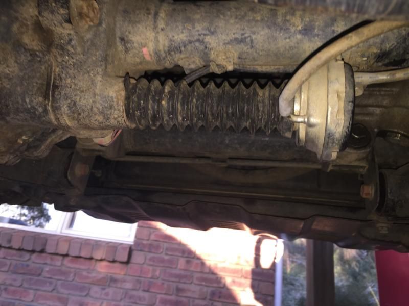
This mod was done on a 2009 ML. if you have a 2013 model it probably will not have the vacuum actuator.
you will need to climb under & have a peek
no actuator means LR2WD has not been done,... yet
I have not looked at the later model so I am of no help
you will need to climb under & have a peek
no actuator means LR2WD has not been done,... yet
I have not looked at the later model so I am of no help
-
Snooozy - Platinum Subscriber
- Posts: 3860
- Joined: Sat Jun 27, 2009 12:27 am
- Location: Victoria
Re: Low range 2wd
![]() by Calblitzen on Sat Jul 05, 2014 5:13 pm
by Calblitzen on Sat Jul 05, 2014 5:13 pm
I believe there is still work to be done to to the later models 2012 on that don't have the actuator to find a solution for 2wd low range. I have a build date of April 2012 and I have no actuator. I believe the workings are all within the gearbox.
No matter what life throws at you, SMILE.
Better to be looking at it, than looking for it.
Better to be looking at it, than looking for it.
-

Calblitzen - Posts: 1054
- Joined: Mon Oct 29, 2012 7:15 pm
- Location: Sydney (south)
Re: Low range 2wd
![]() by triton_guru on Thu Jul 17, 2014 2:19 pm
by triton_guru on Thu Jul 17, 2014 2:19 pm
do you know whether people have been able to activate the factory rear locker with this mod at all?
-
triton_guru - Posts: 865
- Joined: Sat Mar 23, 2013 4:49 pm
Re: Low range 2wd
![]() by paddstar69 on Thu Jul 17, 2014 4:23 pm
by paddstar69 on Thu Jul 17, 2014 4:23 pm
tritonguru
short answer is YES rear diff lock ( factory ) works with this mod wired in correctly.
what you must understand with this mod is the drive train is still in low range 4WD, so its not like you can drive around as normal with a locked rear end. You would quickly be visiting a diff specialist for repairs.
The early bird might get the worm, but the second mouse gets the cheese.
-

paddstar69 - Platinum Subscriber
- Posts: 151
- Joined: Mon Feb 28, 2011 7:00 pm
- Location: Oak Flats NSW
Re: Low range 2wd
![]() by triton_guru on Thu Jul 17, 2014 5:03 pm
by triton_guru on Thu Jul 17, 2014 5:03 pm
what i was thinking is 4h with the mod can allow meto have the rear diff lock on whilst in 2wd
-
triton_guru - Posts: 865
- Joined: Sat Mar 23, 2013 4:49 pm
Re: Low range 2wd
![]() by Jaymac92 on Fri Aug 22, 2014 10:22 pm
by Jaymac92 on Fri Aug 22, 2014 10:22 pm
Soooo... Anyone tried it with a post 2012 model? :p
2013 MN GLR 4x4 with TJM Bullbar, side rails and sliders, TJM Snorkel, Uniden UHF, Black sunraysia rims and more to follow...
-
Jaymac92 - Posts: 125
- Joined: Fri Jun 07, 2013 7:04 pm
- Location: Melbourne
Re: Low range 2wd
![]() by Jaymac92 on Tue Oct 14, 2014 8:48 am
by Jaymac92 on Tue Oct 14, 2014 8:48 am
Bump
2013 MN GLR 4x4 with TJM Bullbar, side rails and sliders, TJM Snorkel, Uniden UHF, Black sunraysia rims and more to follow...
-
Jaymac92 - Posts: 125
- Joined: Fri Jun 07, 2013 7:04 pm
- Location: Melbourne
Re: Low range 2wd
![]() by Jaymac92 on Wed Oct 22, 2014 7:08 am
by Jaymac92 on Wed Oct 22, 2014 7:08 am
Bump
2013 MN GLR 4x4 with TJM Bullbar, side rails and sliders, TJM Snorkel, Uniden UHF, Black sunraysia rims and more to follow...
-
Jaymac92 - Posts: 125
- Joined: Fri Jun 07, 2013 7:04 pm
- Location: Melbourne
Re: Low range 2wd
![]() by biggibbo on Wed Oct 22, 2014 3:17 pm
by biggibbo on Wed Oct 22, 2014 3:17 pm
Doesn't look like it mate. Maybe you need to break out the wiring diagrams and give it a go. Someone needs to be first
-
biggibbo - Posts: 2165
- Joined: Mon Jun 07, 2010 9:20 am
- Location: Newcastle. NSW
Re: Low range 2wd
![]() by Jaymac92 on Tue Nov 04, 2014 9:35 pm
by Jaymac92 on Tue Nov 04, 2014 9:35 pm
Wiring diagrams? Eeeep hahahabiggibbo wrote:Doesn't look like it mate. Maybe you need to break out the wiring diagrams and give it a go. Someone needs to be first
2013 MN GLR 4x4 with TJM Bullbar, side rails and sliders, TJM Snorkel, Uniden UHF, Black sunraysia rims and more to follow...
-
Jaymac92 - Posts: 125
- Joined: Fri Jun 07, 2013 7:04 pm
- Location: Melbourne
Re: Low range 2wd
![]() by oldplodder on Wed Nov 05, 2014 7:08 am
by oldplodder on Wed Nov 05, 2014 7:08 am
Tried the above wiring mod on my 2012 GLX manual, with factory rear diff lock, and no front diff actuator.
Doesn't work.
Doesn't work.
- oldplodder
- Platinum Subscriber
- Posts: 199
- Joined: Tue Sep 23, 2008 8:17 am
Re: Low range 2wd
![]() by Jaymac92 on Wed Nov 05, 2014 8:27 am
by Jaymac92 on Wed Nov 05, 2014 8:27 am
so it is virtually impossible for post 2012?oldplodder wrote:Tried the above wiring mod on my 2012 GLX manual, with factory rear diff lock, and no front diff actuator.
Doesn't work.
2013 MN GLR 4x4 with TJM Bullbar, side rails and sliders, TJM Snorkel, Uniden UHF, Black sunraysia rims and more to follow...
-
Jaymac92 - Posts: 125
- Joined: Fri Jun 07, 2013 7:04 pm
- Location: Melbourne
Re: Low range 2wd
![]() by NowForThe5th on Wed Nov 05, 2014 9:08 am
by NowForThe5th on Wed Nov 05, 2014 9:08 am
I'd say so. Unless someone can come up with a way to separate linkages but that would need some engineering.
Chris
If work is so terrific, why do they have to pay us to do it?
If work is so terrific, why do they have to pay us to do it?
-

NowForThe5th - Moderator
- Posts: 9234
- Joined: Sun Jun 15, 2008 2:00 pm
- Location: Holt, ACT
Re: Low range 2wd
![]() by Jaymac92 on Wed Nov 05, 2014 5:34 pm
by Jaymac92 on Wed Nov 05, 2014 5:34 pm
Mmmm. My mechanic looked under my car then under my bonnet and said he could fit a "tap" for the vacuum.. Which now seems weird haha
2013 MN GLR 4x4 with TJM Bullbar, side rails and sliders, TJM Snorkel, Uniden UHF, Black sunraysia rims and more to follow...
-
Jaymac92 - Posts: 125
- Joined: Fri Jun 07, 2013 7:04 pm
- Location: Melbourne
Re: Low range 2wd
![]() by Scott_ on Sat Jan 24, 2015 6:33 pm
by Scott_ on Sat Jan 24, 2015 6:33 pm
- Scott_
- Posts: 37
- Joined: Sat Aug 24, 2013 5:37 pm
Re: Low range 2wd
![]() by Bigbirdalx on Sat Jan 24, 2015 7:29 pm
by Bigbirdalx on Sat Jan 24, 2015 7:29 pm
Removing vac creates 4wd. Thats why when we turn off it engagez front dif
If im posting, im either on the toilet, at work or both
-

Bigbirdalx - Posts: 677
- Joined: Tue Oct 30, 2012 7:19 am
- Location: northside of brisbane
Return to Drive Train Components
Who is online
Users browsing this forum: No registered users and 10 guests
![]()