Just putting this up in preparation for a how to remove and refit the CV's on a Triton after doing this on Saturday to 4WD26's chasis.
I must say a very big thank you to Lewis, the manager of Jonlin Automotive Engineers in Brisbane who donated his time and expertise and put on a TAFE like training day for some of us numbsculls.
Lewis was the bloke who came to the City View Geek trip with Jop and made a few mates with his enthusiasm and help when a few guys were stuck. I will also give him a wrap for his generosity during the floods, going around with Jop and helping out people for days with his gurneys and equipment - including a stint at my mates business
The good news it is relatively easy...nothing a bit of patience and a six pack wouldn't make tolerable in the field and the tool list is minimal.
On the good side they seem like typical Mitsubishi drivetrain tough, so I don't really expect breakages...although if I do, I hope it's the drivers side as it is probably easier.
CV Removal
Tool List:
Heavy ground sheet/tarp maybe 2 metres square.
Bolt/parts tin
32mm socket
12, 14, 17, 19mm Spanners
Ball Peen Hammer
3/8” socket set preferably containing a uni joint or 12, 14, 17, 19mm sockets
3 x 3/8” drive extensions to make up approx 400mm length
300mm zip ties
Pry bar set
Side Cutters
CRC/WD40
Care must be taken to not lose any of the nuts or bolts or damage any threads.
DRIVERS SIDE
1. Securely stabilize the vehicle and use car stands if possible. Place the removed wheel under the sill of the car as a safety measure.
2. Remove the hub cap using a screw driver and hammer as with any normal vehicle.

3. Remove the hub nut Split Pin using side cutters or pliers.
4. Remove the hub nut using the 32mm socket and an extension pipe if it’s very tight. To stop the wheel spinning put the car in 4wd 1st gear or Park…conversely have someone standing on the brakes.

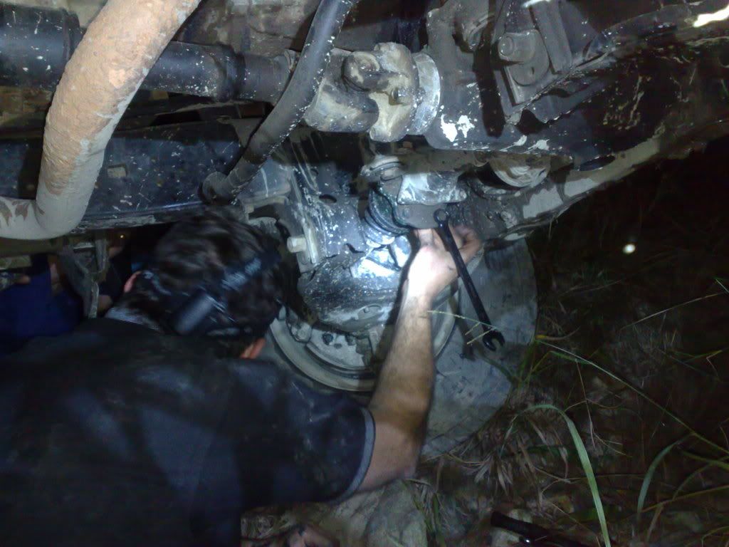
5. Remove the brake line bracket and then the ABS sensor from the hub with the 12mm spanner.
Here the brake line bracket bolt is out and he is removing the ABS sensor.

6. Remove the Tie Rod nut split pin and the top nut with 19mm spanner. Keeping the nut on to protect the thread, hit the end of the tie rod arm housing/loop that the bolt goes through (hard) with a hammer a number of times until the joint "pops". This seems rough but is the best way to do it without damage…if you are desperate or it wont come off replace the nut back on the thread and hit the top of the nut…but this is only if the first option doesn’t work. DO NOT TRY AND LEVER THE TIE ROD OFF AS YOU WILL DAMAGE THE BOOT .


7. Undo the two 17mm brake calliper bolts and lift the calliper up and out of the way. Cable tie it to the strut springs or somewhere clear.


8. Remove the Brake disk – just takes a tap and it will fall off.
9. Upper ball joint removal – place a jack under the lower control arm and jack it up to compress the springs around 10 mm so the suspension is not at full droop. Lever against the strut springs with a pry bar to achieve the same result. This takes the pressure off the ball joint bracket and (3) 12mm bolts. Remove the centre bolt completely. Using a pry bar between chasis and upper control arm to remove tension remove the 2 end bolts a turn or two at a time until they are out – this is because they may still have a little spring pressure on them and removing one totally while leaving one in could potentially damage the last bolt/thread. There is not significant or dangerous pressure here, just potential component damage.


10. Screw the 32mm hub nut ¾ (approx 5 turns) of the way back onto the thread to use as a place to hit the axle/CV with a hammer without damaging the thread. Hit the nut until you see the CV “pop” from the hub housing 5mm or so – it will be loose once this is done.


11. Pull the CV out of the wheel hub – or more accurately pull the wheel hub off the end of the CV and out of the way by twisting left or right.

Notice in this pic the sealed wheel bearing inside the back of the hub. Disassembly to this point would be required to change a wheel bearing.

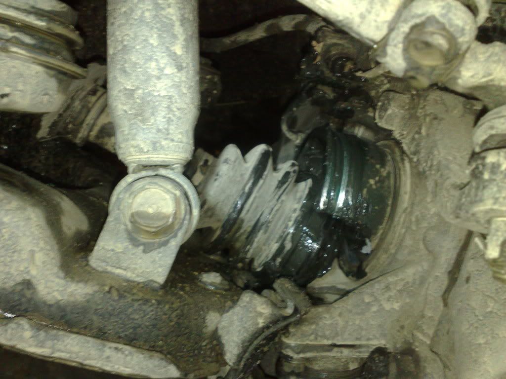
12. Look through to where the CV enters the front axle housing and identify the four bolts on the flange holding the CV to the axle housing. Using a number of extensions to get the reach, undo these bolts with your 14mm socket. If you have access to an air rattle gun or 18volt battery rattle gun use this as it is a nut and bolt and the speed may see the nut come off without spinning the bolt head on the other side (for this reason I would spray the nuts -the side facing you - with WD40 etc and have a beer in the hope they will come off without spinning the whole bolt). If not an angled pry bar is needed to "reach around" (p!ss off Blue) and hold the bolt head. Care must be taken not to damage the threads or nuts as the bolts are loose but “trapped” and can’t be fully removed so if a nut does not go back on to secure the bolt, it will slip backwards until it catches on the larger axle bolts behind here (the non rusty ones) and the wheel will not turn or will shear off when the wheel turns.
Note..these pics were taken from inside the chasis due to light issues for the camera...so is viewed backwards. The rusty bolts are the back of the CV flange bolts that you need to remove

Note the CV bolt slides back but is unable to be fully removed...any thread damage to these bolts to cause a nut not to go on will allow the bolt to do this and as you can see will catch on the axle housing bolts and...bang

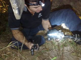
13. Pull the CV out of the axle.


The CV flange after removal

14. Repeat the procedure to replace, but on the passenger side first carefully relocate the CV through the axle housing seal and then the spline into the axle.
PASSENGER SIDE
The steps are the same until step 11. This is a “double shaft” CV and the spline is further into the axle housing. The flange with 4 bolts is not used on this side; it is a slide in fit which means you will have to use a pry bar on the small lip where the flange exits the axle housing and lever the CV out. This is the reason you will need one of the small pry bar kits as depending where you are and the position and access you have available you may need an odd length pry bar to do this.
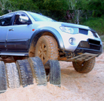
Photo: Driver and passenger CV's...notice the driver side has a 4 bolt flange and passenger is a hub with an extra shaft and spline
Also the CV's are reversed in this photo...thanks Chicky