Essentially, yes. When there's no weight in the back is when the suspension lift is at its maximum and the angles of the drive shaft differ by the greatest amount.
In mine, about 150 kg in the back and the shudder was completely gone. Varies by vehicle though.
Suspension lift....shudder
Re: Suspension lift....shudder
![]() by NowForThe5th on Fri Mar 04, 2016 6:32 pm
by NowForThe5th on Fri Mar 04, 2016 6:32 pm
Chris
If work is so terrific, why do they have to pay us to do it?
If work is so terrific, why do they have to pay us to do it?
-

NowForThe5th - Moderator
- Posts: 9234
- Joined: Sun Jun 15, 2008 2:00 pm
- Location: Holt, ACT
Re: Suspension lift....shudder
![]() by Tasc4life on Fri Mar 04, 2016 6:35 pm
by Tasc4life on Fri Mar 04, 2016 6:35 pm
kxboss wrote:Been told that the shudder is only when no weight in the back ???
Is this true????
The less weight I have in mine the more noticeable the shudder is.
The height of the rear end lowers when weight is increased, lower rear = lower angles at the shaft. Less angle at shaft = less shudder
-

Tasc4life - Posts: 216
- Joined: Sun Nov 15, 2015 2:21 pm
Re: Suspension lift....shudder
![]() by Tasc4life on Fri Mar 04, 2016 6:40 pm
by Tasc4life on Fri Mar 04, 2016 6:40 pm
I'm still hoping to get the TJM centre bearing spacer tomorrow. If I get it, and get it installed, I will throw something up in here to let everyone know..
Not sure on what the kit would do for a factory height/suspension setup....
Not sure on what the kit would do for a factory height/suspension setup....
-
Tasc4life - Posts: 216
- Joined: Sun Nov 15, 2015 2:21 pm
Re: Suspension lift....shudder
![]() by Tasc4life on Sat Mar 05, 2016 10:51 am
by Tasc4life on Sat Mar 05, 2016 10:51 am
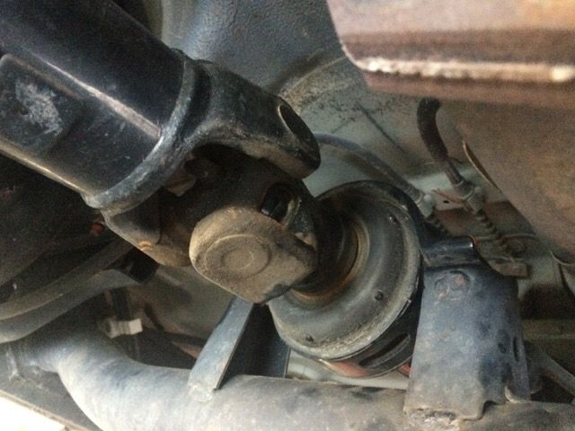
I picked up the centre bearing spacer today! Installed in about 30 minutes.
Happy to report my shudder is gone, both on take off and when gearing down to a stop! Best $100 I've spent! The shudder was driving me crazy! Made me cringe and get frustrated every time I thought about it! I highly recommend it to any MQ with a lift thats suffering from the shudder!
Went from this

To this

Doesn't seem like much, but makes all the difference!
Happy to report my shudder is gone, both on take off and when gearing down to a stop! Best $100 I've spent! The shudder was driving me crazy! Made me cringe and get frustrated every time I thought about it! I highly recommend it to any MQ with a lift thats suffering from the shudder!
Went from this
To this
Doesn't seem like much, but makes all the difference!
-
Tasc4life - Posts: 216
- Joined: Sun Nov 15, 2015 2:21 pm
Re: Suspension lift....shudder
![]() by Kuff on Sun Mar 13, 2016 3:18 pm
by Kuff on Sun Mar 13, 2016 3:18 pm
So did my centre bearing rotate today on my 08 ML. WOW what a huge difference, I was getting a shudder up to about 30km/hr and now it's bearly noticeable. Checked it in 4L as well (only a flat surface) and nothing. It's why I love this forum so much useful information.
I will still losen off the tail shaft at some point and measure the gap to decide which spacer to get as I have seen numerous thicknesses on the market ranging from 13mm to 25mm.
Also to those of you who want to do this, as I have seen some confusion in other comments, when people say rotate, they mean rotate top to bottom not front to back.
It is really a very simple job, I would say getting ready to do the job and tidying up after took longer than the job itself.
Petrol '08 GLX-R
-

Kuff - Posts: 98
- Joined: Sun Sep 13, 2015 7:49 am
- Location: Baldivis (Perth), WA
Re: Suspension lift....shudder
![]() by Rienoh on Mon Aug 22, 2016 9:35 am
by Rienoh on Mon Aug 22, 2016 9:35 am
ML with a 2 piece tail shaft. I have just put Ultimate +50 in the front and the +20's in the back. I have less shudder now than I did with stock rears
I have managed to get it to shudder once in a spot it always did it before.
I had a 1 piece quoted and ready to go aswell hahaha
Guess they don't all do it.
- Rienoh
- Posts: 89
- Joined: Sun Jul 05, 2009 4:40 pm
- Location: TOWNSVILLE
Re: Suspension lift....shudder
![]() by Staf77 on Mon Aug 22, 2016 11:39 am
by Staf77 on Mon Aug 22, 2016 11:39 am
Just recently put in a 2 inch lift and wondering if anyone had an issue with shudder on a one piece tail shaft? I have an ML Auto and slight shudder under heaving acceleration from a standing start but it is noticeably worse when turning right or left under heavy acceleration from a standing start.
- Staf77
- Posts: 65
- Joined: Thu Mar 13, 2014 4:08 pm
Re: Suspension lift....shudder
![]() by Bertk on Mon Jul 31, 2017 10:24 am
by Bertk on Mon Jul 31, 2017 10:24 am
To everyone with a Lifted MN manual and suffering the long term problem of shuddering on take off...I have tried and bought everything to get rid of it with the 2 piece tail-shaft...I now have had a one piece tail-shaft made to suit ( they make it to suit the new height), and now do NOT experience any shudder at all 100% gone....
Save your money dont buy spacers, wedges....just get the one piece shaft...
Save your money dont buy spacers, wedges....just get the one piece shaft...
- Bertk
- Posts: 2
- Joined: Mon Apr 20, 2015 12:12 pm
Re: Suspension lift....shudder
![]() by deermaster on Mon Jul 31, 2017 5:52 pm
by deermaster on Mon Jul 31, 2017 5:52 pm
Bertk wrote:To everyone with a Lifted MN manual and suffering the long term problem of shuddering on take off...I have tried and bought everything to get rid of it with the 2 piece tail-shaft...I now have had a one piece tail-shaft made to suit ( they make it to suit the new height), and now do NOT experience any shudder at all 100% gone....
Save your money dont buy spacers, wedges....just get the one piece shaft...
Me too, new tailshaft one piece. No shudder ever, weight or no weight. Yahoo
-

deermaster - Posts: 864
- Joined: Sat Dec 10, 2011 8:03 pm
Re: Suspension lift....shudder
![]() by als1200 on Mon Jul 31, 2017 6:00 pm
by als1200 on Mon Jul 31, 2017 6:00 pm
Is your clearance ok with the1 piece?
- als1200
- Posts: 128
- Joined: Thu Aug 20, 2015 6:11 am
Re: Suspension lift....shudder
![]() by deermaster on Mon Jul 31, 2017 9:06 pm
by deermaster on Mon Jul 31, 2017 9:06 pm
als1200 wrote:Is your clearance ok with the1 piece?
No worries at all.
-
deermaster - Posts: 864
- Joined: Sat Dec 10, 2011 8:03 pm
Re: Suspension lift....shudder
![]() by carrrake on Tue Aug 01, 2017 10:00 am
by carrrake on Tue Aug 01, 2017 10:00 am
So what's the cost of custom 1 piece tail shaft. Could be opportunity for a group buy??
- carrrake
- Platinum Subscriber
- Posts: 85
- Joined: Sun Apr 10, 2011 1:34 pm
- Location: Wickham, WA
Re: Suspension lift....shudder
![]() by deermaster on Tue Aug 01, 2017 6:09 pm
by deermaster on Tue Aug 01, 2017 6:09 pm
carrrake wrote:So what's the cost of custom 1 piece tail shaft. Could be opportunity for a group buy??
I think mine cost me about $350 added to the lift I got at the time and also the fitting of a winch etc etc.
-
deermaster - Posts: 864
- Joined: Sat Dec 10, 2011 8:03 pm
Re: Suspension lift....shudder
![]() by twig on Fri Sep 28, 2018 10:31 am
by twig on Fri Sep 28, 2018 10:31 am
I have a MN manual, EasySelect. These reports of shuddering are putting me off investing in a lift.
I'm curious about the single piece shaft conversion. There is a cross member between the chassis rails that holds the centre bearing between the two pieces of the existing shaft. Do they cut this away? It looks like it would definitely foul a one piece shaft between the transfer case and diff when the rear was compressed, or is a 2 inch lift going to bottom out before that point?
I've been looking at Ultimate as they have good name on here, approx $2k for the kit. But then holy s**t look at this item:
TAIL SHAFT SPACER
MLTSS-TRITON Tail Shaft Spacer for manual �easy select� gearbox $1645.00
For a spacer? Surely that's a typo.
https://www.ultimatesuspension.com.au/v ... icle_id=80
If it is indeed only $350 for a one piece shaft that would seem to be the logical option.
- twig
- Posts: 13
- Joined: Tue Oct 15, 2013 11:42 am
Re: Suspension lift....shudder
![]() by Maxiy on Fri Sep 28, 2018 10:37 am
by Maxiy on Fri Sep 28, 2018 10:37 am
Hey
I have a 2inch ultimate kit in my manual MN, i had the spacer installed at the time, as they experience some shudder on take off. pretty sure the spacer only cost my $150 bucks.
there was very slight shudder on take off when i picked it up, but dont even notice it now.
I have a 2inch ultimate kit in my manual MN, i had the spacer installed at the time, as they experience some shudder on take off. pretty sure the spacer only cost my $150 bucks.
there was very slight shudder on take off when i picked it up, but dont even notice it now.
- Maxiy
- Posts: 544
- Joined: Mon Aug 11, 2014 1:29 pm
Re: Suspension lift....shudder
![]() by Dave on Tue Oct 02, 2018 11:44 pm
by Dave on Tue Oct 02, 2018 11:44 pm
Yeah I have a 2" ultimate kit in a manual ML - the spacer eliminated 99% of the vibration, highly recommended if you decide to lift your Triton.
-

Dave - Site Admin
- Posts: 1970
- Joined: Sun Oct 07, 2007 2:00 pm
- Location: Perth, WA
Re: Suspension lift....shudder
![]() by Enid_Triton on Mon Jun 03, 2019 6:11 pm
by Enid_Triton on Mon Jun 03, 2019 6:11 pm
Old post, but I got this crappy vibration in my mn just recently after a 2" lift.
I worked it out by measuring the Uni-joint angles & then adding castor shims to get the pinion & rear shaft as close as i could to perfect, I also dropped the gearbox by 2.5mm so I could just get the top half of the tail shaft entering the center bearing at (what I think is ) a decent angle. Doing this was not really necessary but I'm finicky, and it does help.
But the best thing I did by far was to add a set of heavy steel drawers in the back to give the old girl a constant load.
Also, the top half of the tail shaft angle is not all that critical, although it is desirable to get it fairly level (but definitely not pointing upwards), think of it as just being an extension of the drive shaft, even if it's sloping down by 4 degrees
The Uni-joints on the bottom half of the two piece tail shaft are the ones you need to worry about and to find out what working angles they are at now you measure the angles on either side of the Uni-joints. This means for the top uni-joint you measure the angle of the top half (or the small tail shaft tube) on the other side of the bearing and then you measure the angle on the lower side of the bearing on the long tail shaft tube. Then subtract lowest angle from highest. The answer you get is the present working angle of that uni joint.
EDIT: I decided to rewrite this next part to make it simpler to understand, how I worded it before even confused me:
So, using the above as a reference lets assume that the drive angle is 4 deg down and now lets say the top half of the shaft is at 10.5 deg down we subtract 4.0 from 10.5 which gives us the working angle of 6.5 degrees. 10.5 - 4.0 = 6.5 degrees
To find the angle of the second Uni-joint we measure the angle of the top tail shaft which we already know is 10.5 degrees and we also measure the angle of the bottom half of the tail shaft, let’s say that is at 11.5 degrees. So now we subtract 10.5 from 11.5 which gives us 1.0 degrees and that is the working angle of the second Uni-joint. 11.5 - 10.5 = 1.0 degrees
Now once you have those two measurements you can work out exactly what your pinion angle needs to be set at to be correct. This may seem a little confusing for some but please preserver because although it may seem complicated, in reality it is really very easy to do.
We just need to find the difference between out first two operating angles that we just worked out.
We take our first operating angle & subtract our second operating angle from it.
Since our first operating angle is 6.5 degrees and our second angle is 1.0 degrees the math looks like this:
6.5 - 1.0 = 5.5 degrees.
So there you have it, to get a perfectly in harmony two piece tail shaft you set your pinion angle at 5.5 degrees and your vibrations will be gone.
Now, here is the formula to work out how much you need to change the present angle of your pinion-shaft from where it is sitting now to get to this magic angle of 5.5 degrees.
All you need to do to find this angle is to subtract the second tail shaft angle you worked out earlier from the angle that the tail shaft needs to be.
In this example we know the pinion angle needs to be set at 5. 5 degrees and we know that the second tail shaft angle we worked out earlier is 1.0 degree. So, you just subtract 1.0 degrees from 5.5 which gives you 4.5 degrees.,
The Math is - 5.5 - 1.0 = 4.5 degrees. This means that you need to change the present pinion angle by 4.5 degrees from where it is now using castor spaces under the leaf springs. It really is that simple, and it worked perfectly for me.
But just remember that the angles I have used above are just examples to show you how it is done, & your Triton tail shaft angles will be totally different from these and hopefully closer to being uniform than the ones I randomly picked.
Also, Please note:if you have part of your shaft that points upwards instead of down you have to work it out differently, and although it is simple to do also I will not bother with it here as it just might confuse the process. But if you need it PM me and I will give you the formula to do it. Also for those who think that the pinon angle and driveshaft angle need to be exactly the same as each other to get the shaft in phase, well, that is true on a one piece tail shaft, but even though uniformity it is desirable with every angle measurement on any tail shaft it's not critical on a two piece. Just by working out the pinion angles as we did above gets it where it needs to be.
Also rotating the center bearing may work for some people but the theory that it lowers the center bearing is nonsense.
Has anyone ever bothered to measure the height differences of the actual drive shafts with the bearing Rotated? Well I have and using the cross-member that it sits on as a base to measure from and with the center bearing rotated it actually raises the the bearing & the drive shafts by close to 6mm.
No wonder so many people get confused with this tip.
Hope this helps.
Last edited by Enid_Triton on Wed Jun 05, 2019 7:46 am, edited 2 times in total.
-

Enid_Triton - Posts: 76
- Joined: Fri Dec 14, 2018 1:38 pm
- Location: Brisbane
Re: Suspension lift....shudder
![]() by Enid_Triton on Tue Jun 04, 2019 6:14 pm
by Enid_Triton on Tue Jun 04, 2019 6:14 pm
One more thing that no one bothers to tell you:
There is a small rubber gearbox mount on the left side of the manual transmission that attaches to the chassis rail, and it breaks inside very easily.
I do not know if the lift causes it to break but it sure can make your gearbox vibrate/shake like crazy under load and take off, if it is broken. It is especially noticeable inside the cab at the gear leaver.
It is not the main cause of the vibration that everyone seems to get with a lift, but it does make that vibration a lot more noticeable.
I took my broken one out, cleaned it really well inside with thinner & wax & grease remover, then I placed it on a piece of plastic, then I centered the rubber piece in its round frame and lined up the broken rubber arms inside it I had to put a couple of spacers/washers under it to get the center bolt tube perfectly centered. Then I just sikaflexed it in 30mm wide sections all they way around from the rubber center to the outside frame so the weak little rubber arms are sitting in the middle of the sikaflex sections.
It has worked great so far & it is a lot stronger than the original & the replacements. But anyway they only cost around $20 bucks new. I think its called a Transfer Case Roll Stopper
-
Enid_Triton - Posts: 76
- Joined: Fri Dec 14, 2018 1:38 pm
- Location: Brisbane
Who is online
Users browsing this forum: No registered users and 5 guests
![]()