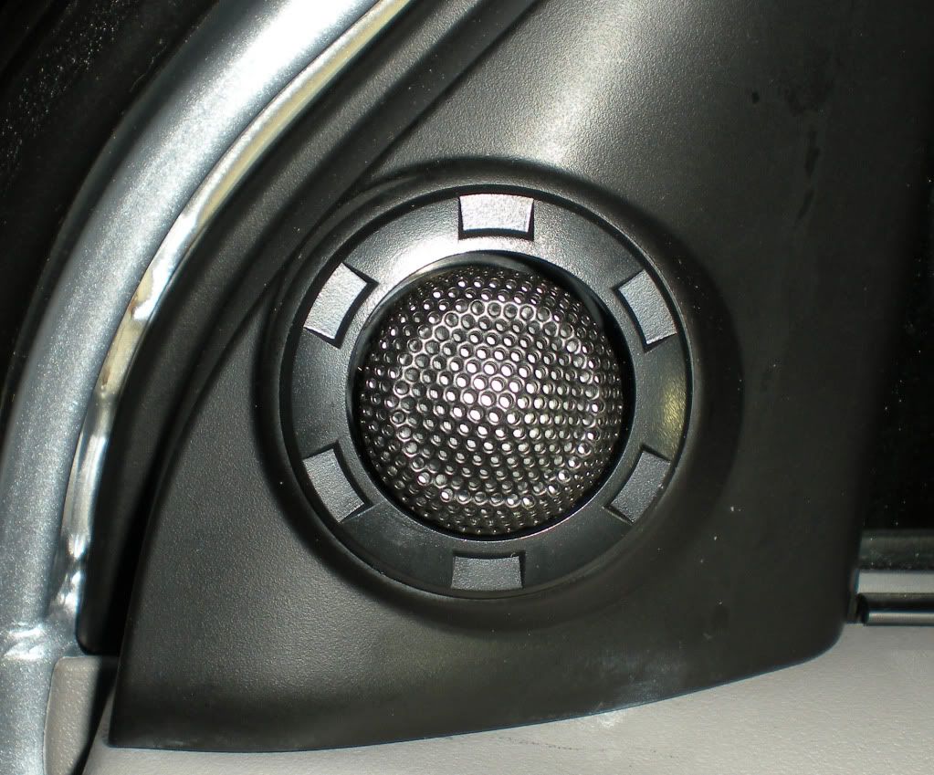
Connect an amplifier to the stock wiring harness behind the MMCS without cutting any of the original wiring. As a related task I upgraded the speakers in the doors as well. Some wires got cut in that process I’ll admit.
This may well be the longest post ever, so apologies in advance. Hopefully it's worth it. If you're not into it just close the window/tab without reading further. Lots of images so not good for dial-up. Sorry about that chief...
Ingredients:
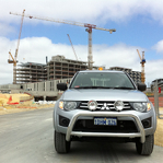
1 x MN GLXR Triton with Kenwood MMCS
1x Cerwin Vega mobile 400.4 amplifier (BYO…)
16 metres or so of decent speaker wire
1 x 12v+ power cable
1x 40 amp self resetting circuit breaker
4 metres of plain wire for 12V ACC and 12V ground from head unit
3 crimp ring terminals for the 12V+ cable connections
Lots of solder, heat shrink, electrical tape, gaffer tape and cable ties
3m of 7mm split loom
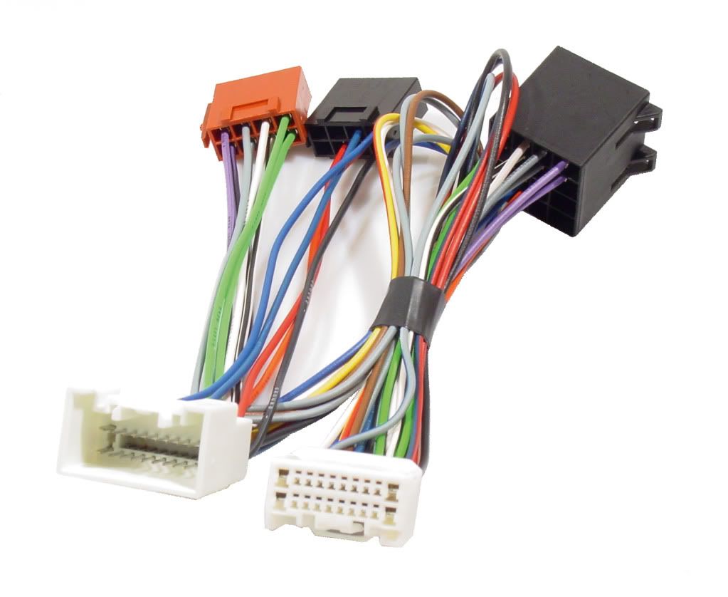
1x ASP-KRAM 86151 – this is a harness for connecting parrot handsfree but importantly it has the 20 pin male and female plugs needed to match the back of the MMCS and the vehicle wiring harness. It gives you speaker outs in an ISO plug and speaker connections back to the vehicle again in ISO plugs.
http://www.getprice.com.au/ISO2CAR-Cable-for-Mitsubishi-and-others-Pls-see-compatibility-ASP-KRAM-86151-Gpnc_99--39321826.htm
I got mine from dstore.com.au but the link above was cheaper when I came to do this write up. Hopefully the link still works for the life of this post.
1x Universal female ISO connector from Aerpro – APP7200 – for connecting speaker wires to
http://www.aerpro.com.au/list.php?pcode=APP7200&cat_name=harnesses&cat_no=10&product_name=Universal+Female+ISO+Connector&cat_sno=160
1x Universal male ISO connector from Aerpro – APP7201 – as above, but in the other direction
http://www.aerpro.com.au/list.php?pcode=APP7201&cat_name=harnesses&cat_no=10&product_name=Universal+Male+ISO+Connector&cat_sno=160
Tools:
Wire strippers
Soldering iron
Tiny screwdrivers
Assorted sockets and/or ring spanners
Phillips head screw drivers, 1 short stubby one and one long
Small (but not tiny) flat bladed screw driver
Magnetic parts tray (optional I guess)
Trim levers or similar to assist in removing the MMCS shroud
Side cutters
Hex keys (for me anyway since my amp terminals used them)
Lighter or similar for heatshrink
Scissors (heatshrink again)
A magnetic recovery tool for when you drop screws down into the dash…
A piece of wire or string to use as a pull through for running cables
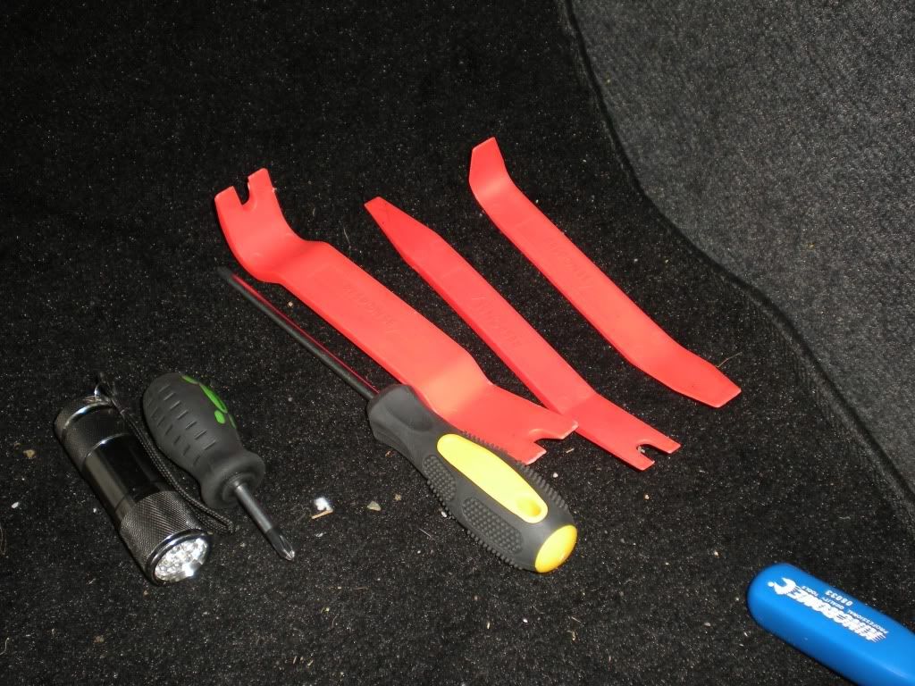
Some tools – the orange levers are great for dash and trim removal:
Recipe:
As with any recipe the end result is all in the preparation. I made some errors along the way but because of that hopefully you won’t make the same ones.
Custom harness
This Kram thing is the only product I was able to find which had the exact style of 20 pin plug in both male and female that we need to match the back of the MMCS and the vehicle harness. I tried metra, aerpro and several other brands before stumbling on this thing quite by fluke one night on ebay – it popped up on one of those suggested sells that are outside ebay.
The main issue to watch out for here is the KRAM harness – it’s not labelled correctly. Each wire has some faint writing on it. Some of the writing is correct and some of it isn’t. It’s the ‘isn’t’ that becomes the problem. The speakers are correctly labelled so don’t worry about those too much.
The ISO speaker plugs are labelled correctly and the colouring is to an international standard (the IS in ISO I guess). So hard to stuff that bit up. The trick is more in the other wires that come off to the other ISO plug. I wanted to use those to switch on my amp (12V+ ACC) and to supply a 12V- to my speaker inputs (because the amp has a hi-level to low-level converter built-in and it needed a 12V- connection to run with the speakers). Chances are you won’t need this 12V- but you may want the 12V+ACC.
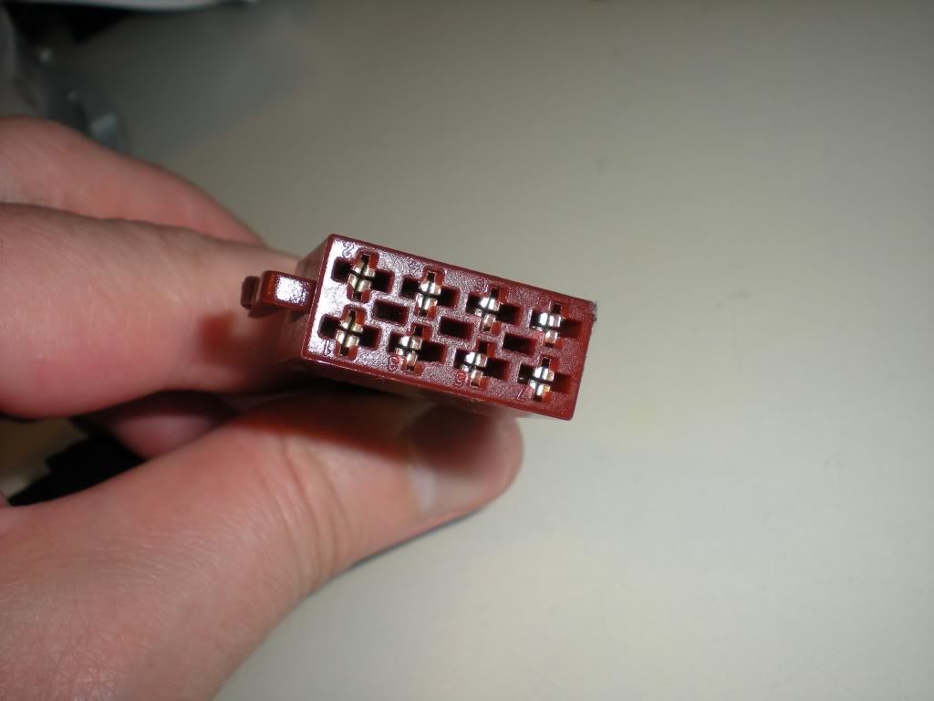
Using the MMCS manual and studying my wiring, I’ve created a diagram that shows the 20 pin plug, looking into the end of the female plug, upside down (sorry about that). I’ve labelled the squares not only with the colour of the stock wire that is connected but also with the purpose and the colour of the wire on the Kram harness that I eventually matched it to. You can match the diagram to the male plug just by lining your two plugs up and comparing them. Diagram below:
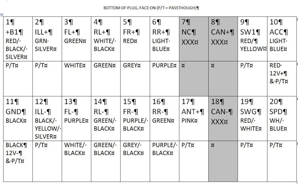
The grey squares have no pins in them. I guess that is where the vehicle interface is connected in models that show climate control and so on via the MMCS. No such luxury for us.
What you need to do is find the couple of pins that don’t presently get a straight connection through (I’ve used the abbreviation P/T for passthrough) and give them one. You should be able to remove a couple of pins from the greyed squares and join them up so that whatever they’re carrying runs straight from the female plug to the male plug. You should end up with a couple of left overs to keep for another day.
For the most part the pins will come out of the plugs fairly easily if you can get a fine jewellers type screwdriver in to dislodge the metal or plastic tabs that hold them in. I say for the most part because I came across one pin that I just couldn’t shift. The female side of the ISO connectors are even worse, they need a special tool that I just didn’t have. The male blade style ISOs are a bit easier.
If you’re taking power from the unit now is the time to pay attention to which wires are connected to the non speaker iso plug. Make sure the ones you are using are connected to what you need by reference to my diagram and not by reference to the labels they carry on the Kram product.
What you do in terms of connecting the speaker wiring to the ISO plugs is simple enough. I cut 8 equal lengths of paired cable. I think they were about 2 metres long each. Divide these into 2 sets, one out of the MMCS and one to the car harness. The ISO speaker plugs should have 8 speaker wires in coloured pairs. The striped wires are the negatives. I found it was a good idea to label the free ends with a piece of red electrical tape folded back on itself and a black texta. That made sure I connected the correct pairs to the correct places on the amp.
The other ends will depend on your amp setup. The amps I’ve mostly seen have terminal type outputs so your amplified speaker wires can have bare ends for connecting to the amp. In my case the others had to be wired to a little OEM plug for the amp.
More commonly you may need to be connecting these wires (out from the MMCS, in for the amp) to a converter that converts high level signal to line level before inputting it to the amp.
If you’re in the high/low level boat you may need something like this:
http://www.jaycar.com.au/productView.asp?ID=AA0480
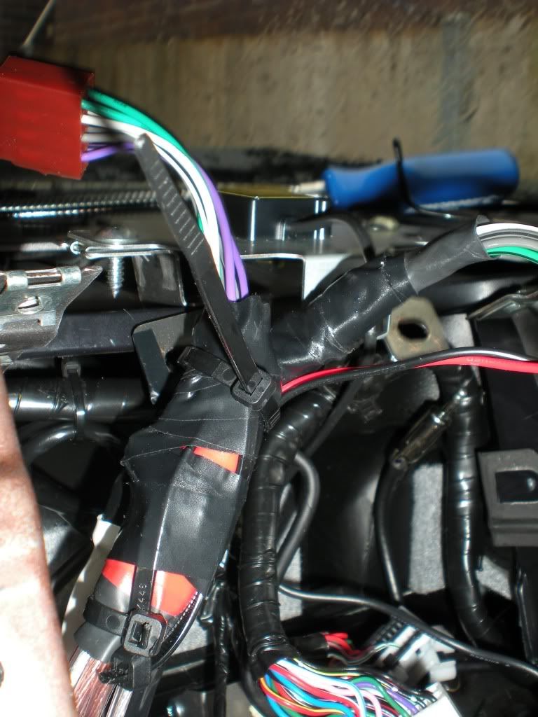
Here’s a few shots of my harness when it was finished.
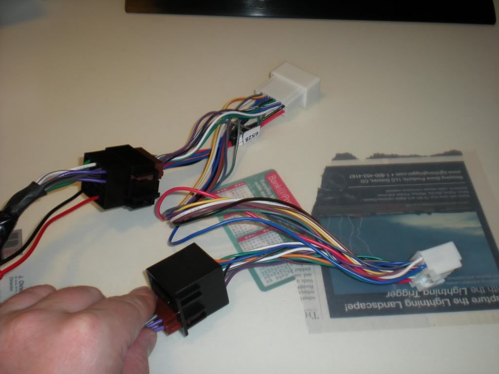
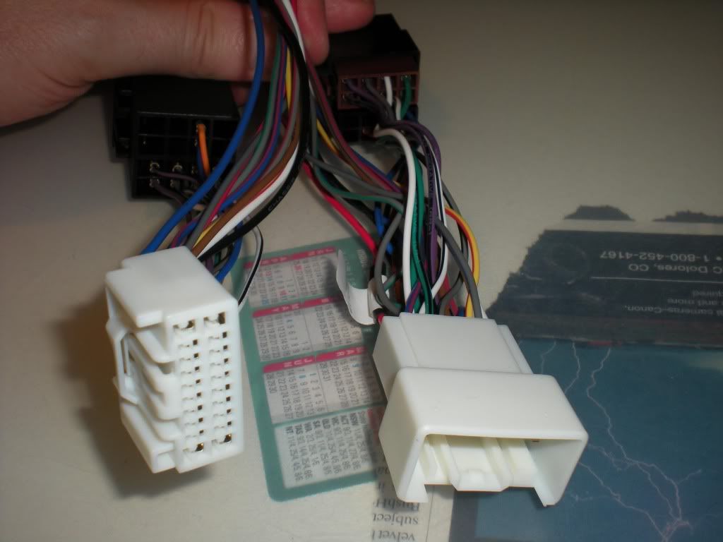
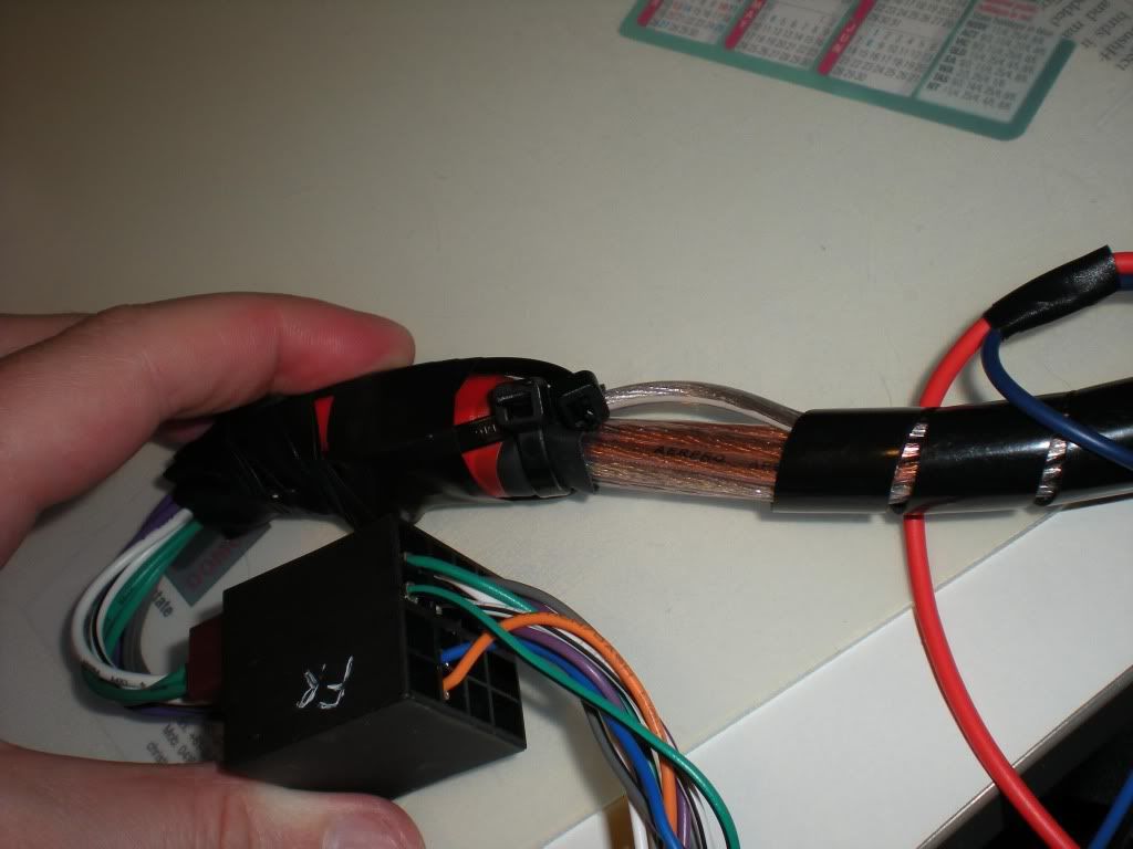
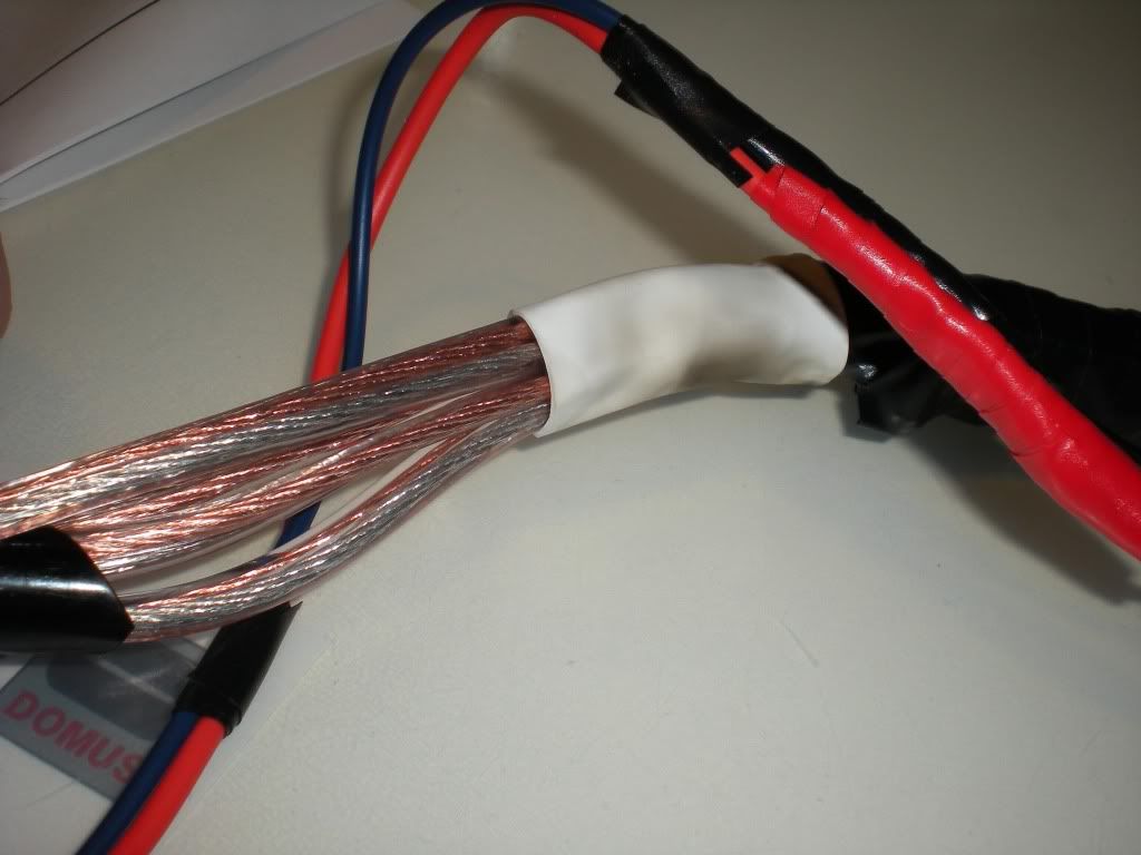
I called it FrankenHarness and it’s not too hard to see why. It’s not pretty, but once it was done it did the job perfectly.
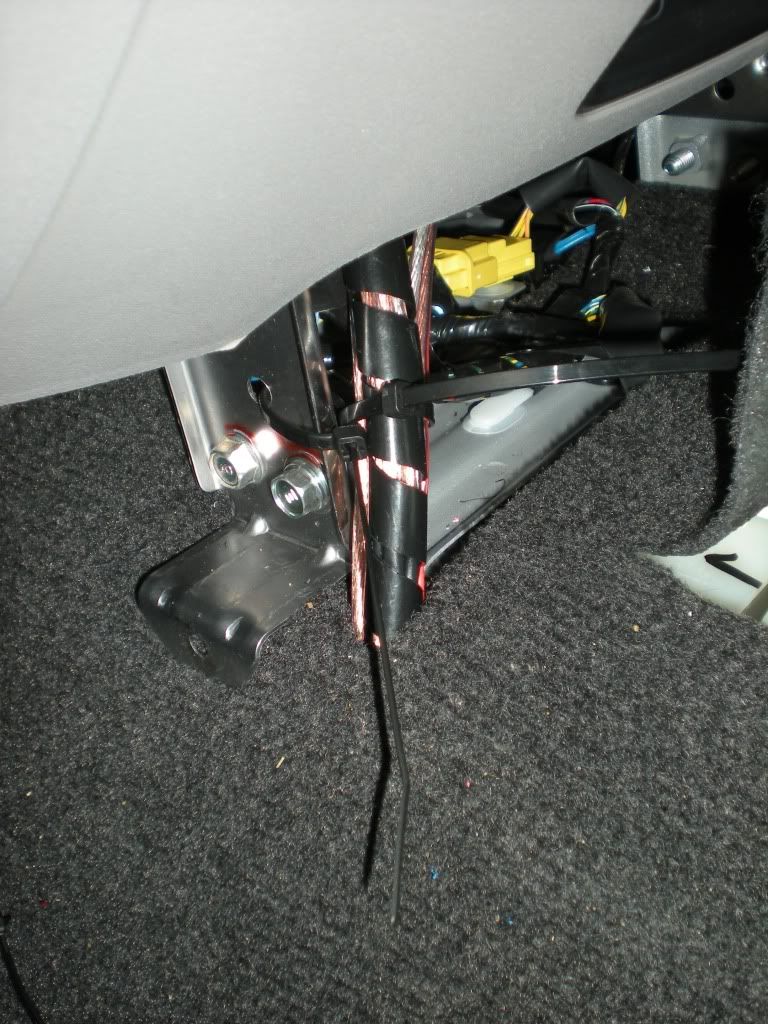
One thing I did near the ends was to add some reinforcing so that I wouldn’t be pulling the cable through with pressure on the soldered joints – there’s some pictures of this later during the install phase but it’s also what depicted above with the odd looking cable tie arrangement. I had multiple layers of heatshrink tubing over the various joints and then one big sleeve sort of arrangement. I wrapped a cable tie tightly around the whole bunch either side of the joins and then looped 2 cable ties through the 2 tight cable ties. The end result is that the tension is on the cable ties rather than going through the wires and putting pressure on the joints (not that my soldering was too dodgy but who wants to chance it?).
The install
Remove the MMCS. First remove the shroud. See the commentary in the forum thread titled ‘taming the mmcs’ for advice on that http://www.newtriton.net/phpbb/viewtopic.php?f=21&t=4480&p=66832&hilit=taming+the+mmcs#p66812. It’s plastic and held in place mostly by some clips across the back near the windscreen and some across the bottom of the MMCS at the front.
Just for the hell of it here are some shots of the shroud once it’s off so you can size it up for yourself:
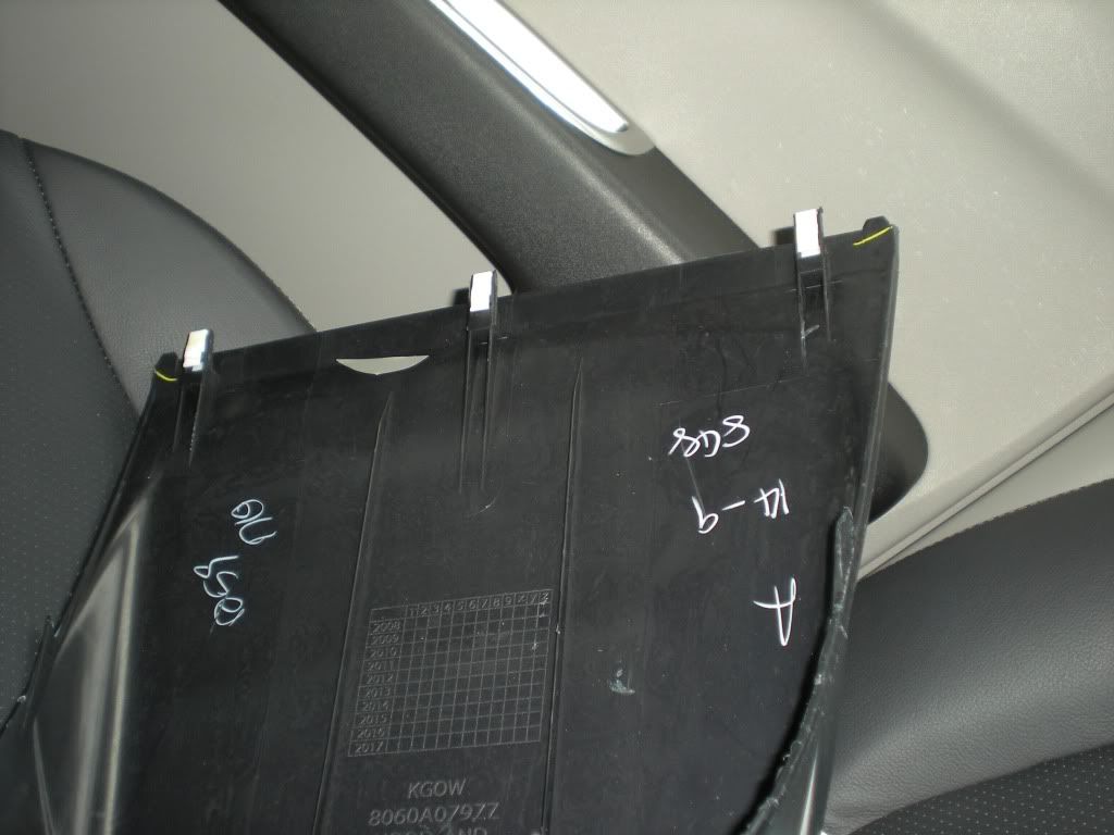
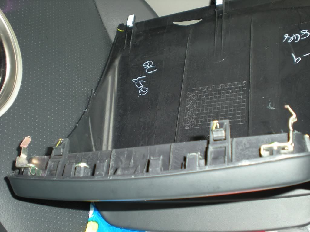
The front/bottom edge of mine looks different to what yours will because I have removed 2 small metal tabs that look a bit like those that still show up on the second image above.
Here’s some rough shots of the uncovered MMCS (that’s the GPS antenna all on its own up the top there):
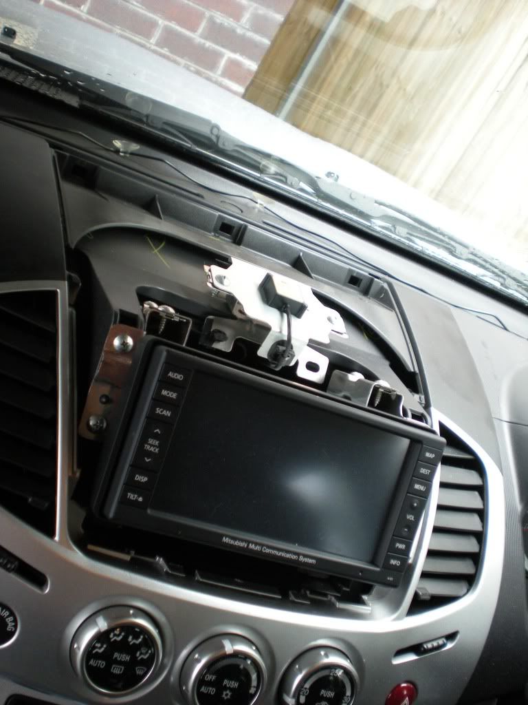
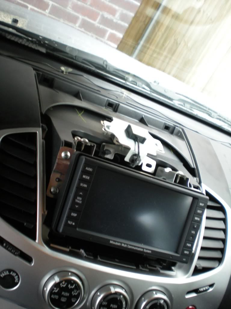
There are then 4 screws on top, 4 on the sides and 2 at the bottom holding the MMCS in. Remove all of these and whack them in your magnetic tray. The bottom ones are the 2 most likely to get dropped so be careful here. I am still missing one of mine…
Lift and pull it forward to expose the wiring.
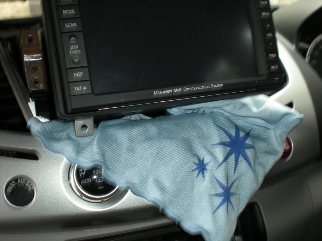
I recommend sticking a rag or something similar over your dash and under your MMCS while it is sitting there and you’re stuffing around with the wires. This should help stop you scratching the dash if you bump the MMCS with your arm (which will happen).
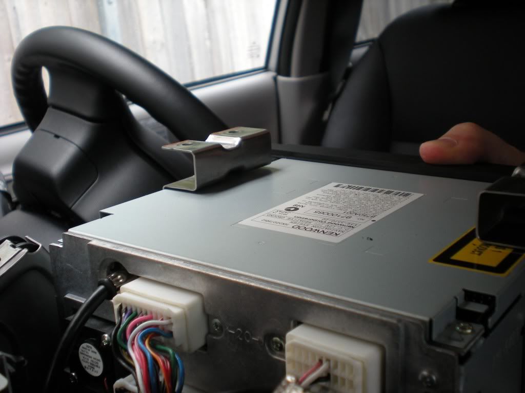
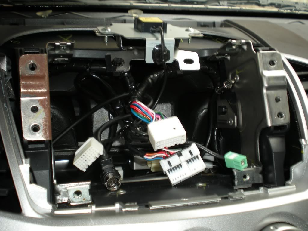
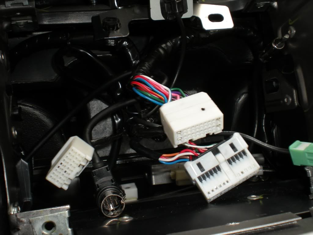
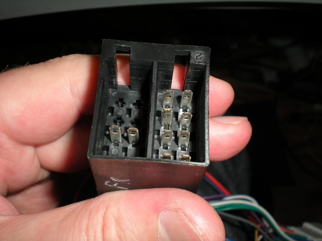
Each of the plugs has a tab or a lock of some sort on it, they will not come out unless you squeeze them right, even the ipod cable. The two top white plugs have their tabs on the bottom. The other black and white plug has its tab on top. The ipod cable has a tiny little tab on the driver’s side. The green GPS plus has a tab on the bottom and the antenna plug just needs a bit of force to pull it out – watch you don’t slip and skin your knuckles on the bracket behind when you are pulling that one out. Remove all of them. Your back panel will look like this:
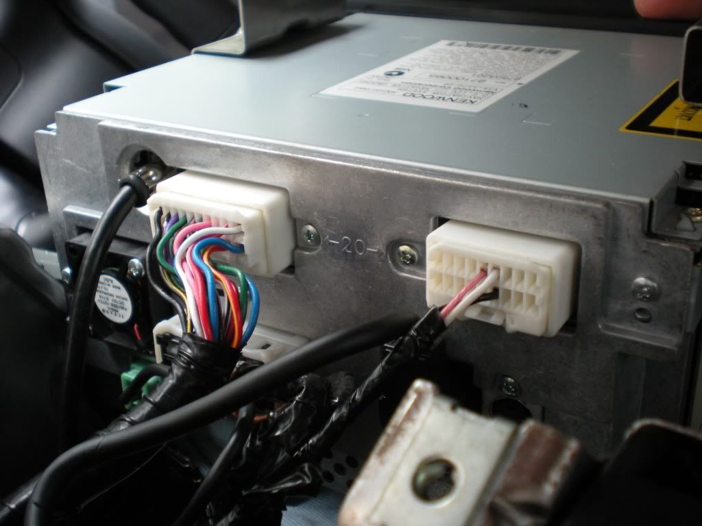
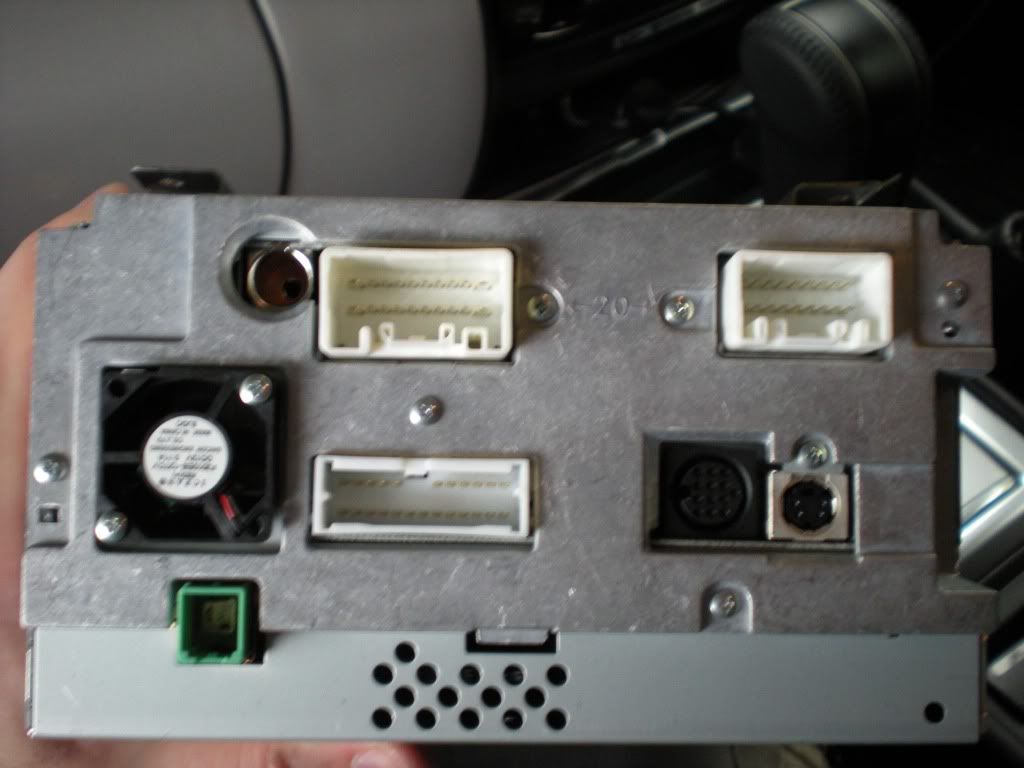
For those coming later and wondering what all those plugs are here’s a close up or two since I’m in there with a camera and all.
Close up of the s-video style output which is apparently a 5.1 spdif output on some models:
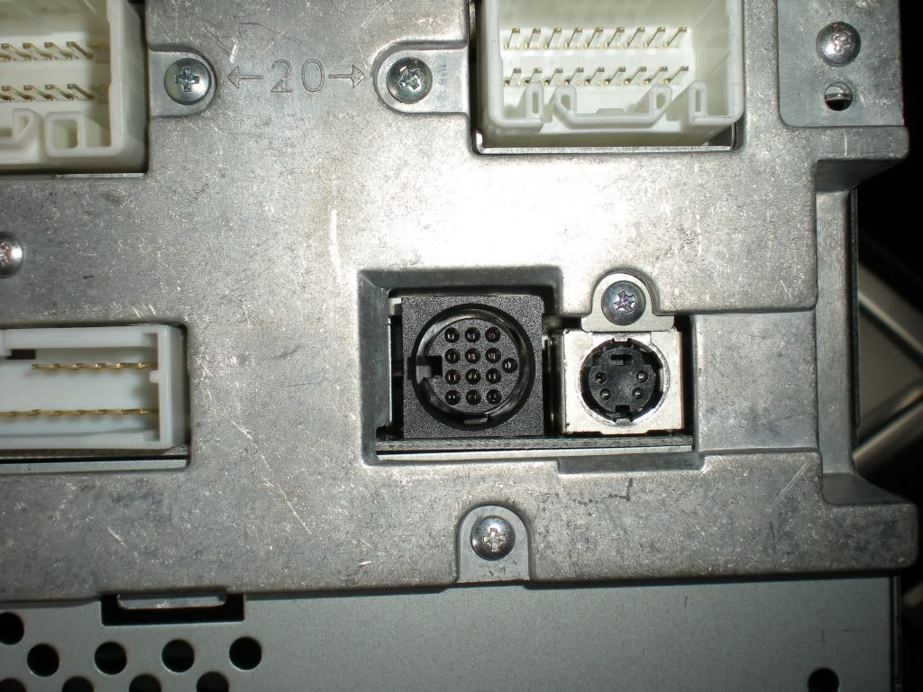
The larger round plug next to it on the left is the ipod connector (google resourceit for a cheaper cable than Mitsu). The rectangular plug above it is I think an 18 pin plug like so:
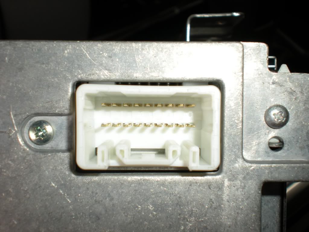
This should only have about 3 wires connected. I think they run to the audio inputs in the centre console (but not the video). The other pins on this plug are used in other models to connect to the rear seat entertainment units apparently.
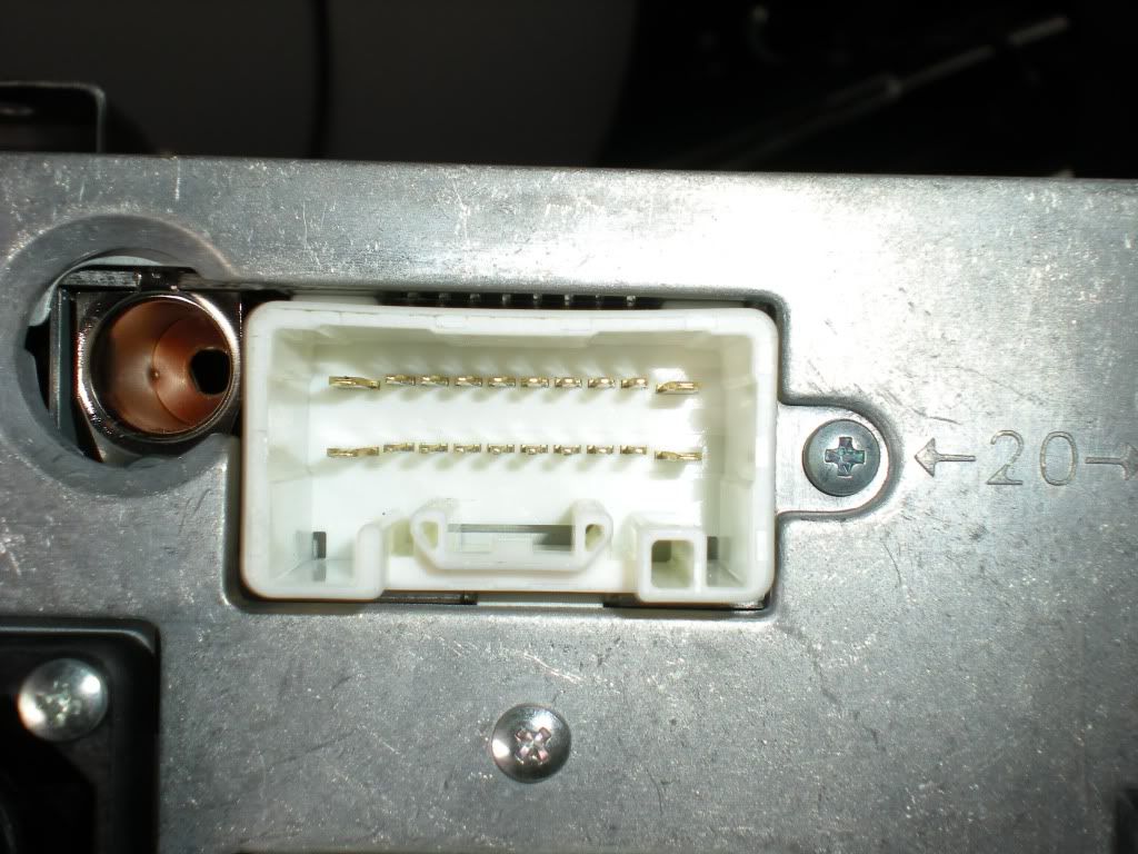
Antenna hole and the 20 pin connector we’re going to play with:
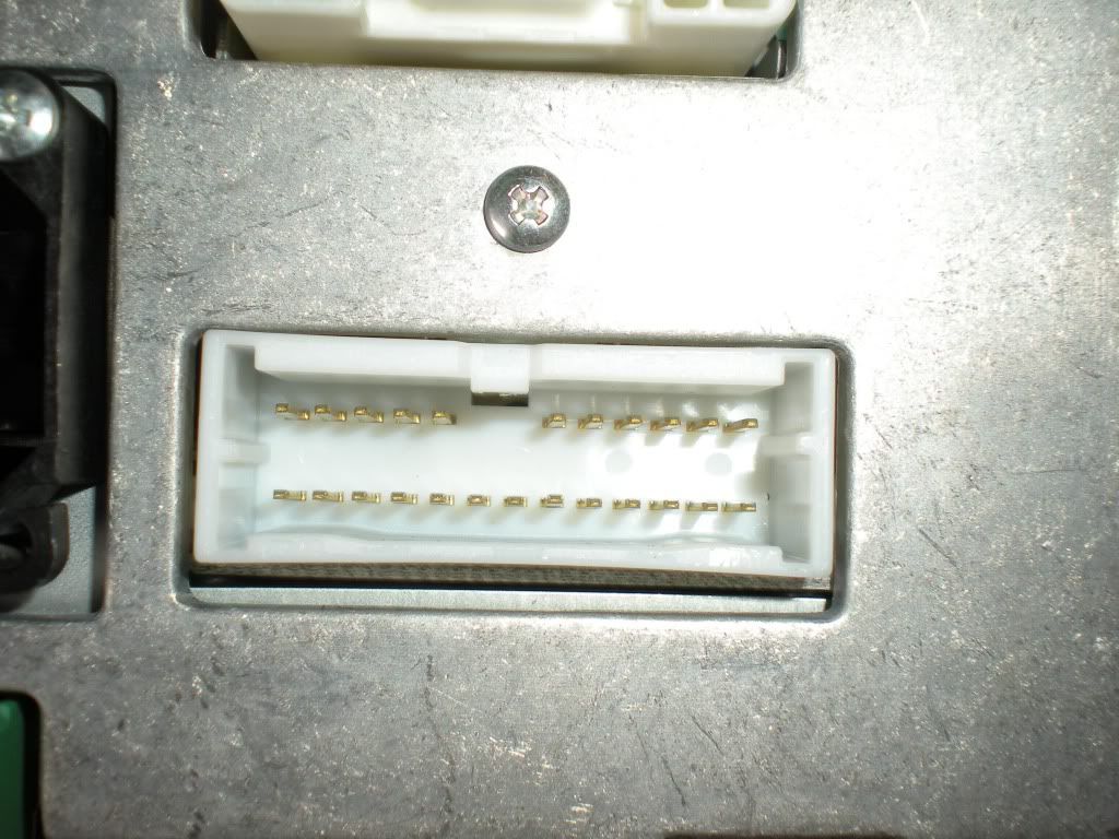
24 pin plug – we play with this if installing the rear view camera using mitsubishi’s harness:
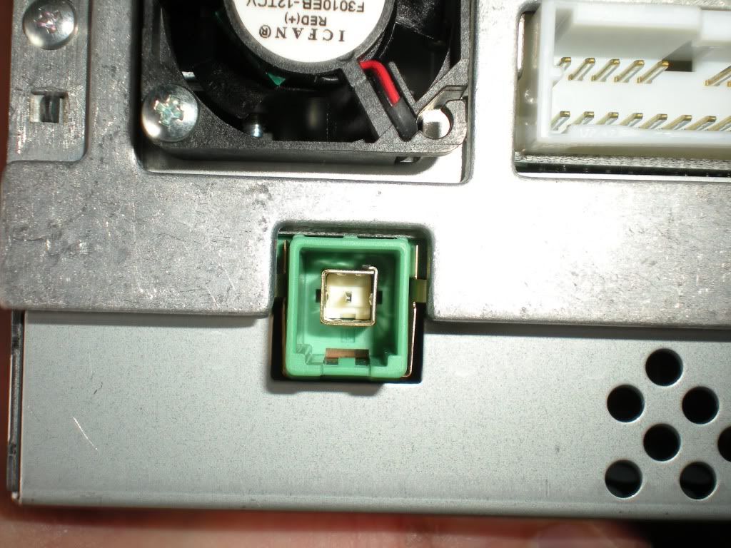
Green plug is the GPS plug and a close shot of the little cooling fan (which is noisy if your engine is off and your volume low):
Once the cables are all unplugged you can remove the MMCS altogether and put it somewhere safe. You’re going to make a mess in the front so stick it behind the driver’s seat, that’s where I stuck mine.
The wires are bundled into 2 main bunches which are secured by small black clips into that metal bracket under the GPS antenna. I found it best to squeeze those clips back through the hole so I had more slack in the cabling when plugging the MMCS back in later. One of them (the right) is off in the photos below. It also gave me more freedom to inspect the 20 pin plug in the harness. Some random shots of the wiring mess follow:
If you’re looking closely you might notice that I have put black tape on the metal bracket on the left – it was rubbing some of my wiring so I wanted it less sharp. My 24 pin plug may look different to yours by 3 wires if you don’t have the reverse camera installed.
If you then look at the hole it came from you’ll see a metal plate. Towards the back left corner as you face the front there is a square hole maybe an inch square. You can just see it in the background of the shot with the rusty bracket above. Why is it rusty already?
This is where you will run your cables. It has sharpish edges on it. If you’re clever you’ll whack a couple of bits of tape on the edges now before pulling anything through or scraping your finger on it. I didn’t but wish I had. Luckily my wires had nice thick insulation on them so no great loss.
Right, now at this point it’s time to get a little more hard core.
First, disconnect the negative on the battery. Don’t take a shortcut here we’re about to go near airbag wiring so it’s not worth it. Disconnect the battery – you know you should. Did I mention disconnecting the battery? Just do it. Last warning….
Second, remove the passenger seat. This is not fun.
There are 2 nuts and 2 bolts to remove. Slide the seat back on its rail and tilt the seat itself forward. Undo the two nuts at the front. I used a little ratchet ring spanner but a socket would be just as good. Once they’re off slide the seat forward again so you can access the rear bolts. They’re under some plastic covers that pull out of the way without too much trouble. I snapped a little piece off one of mine but it still sort of sits where it should. You might be more careful/skilful. Once the bolts are out, gently slide the seat back on its rails before tipping it off the front studs.
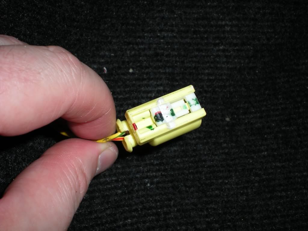
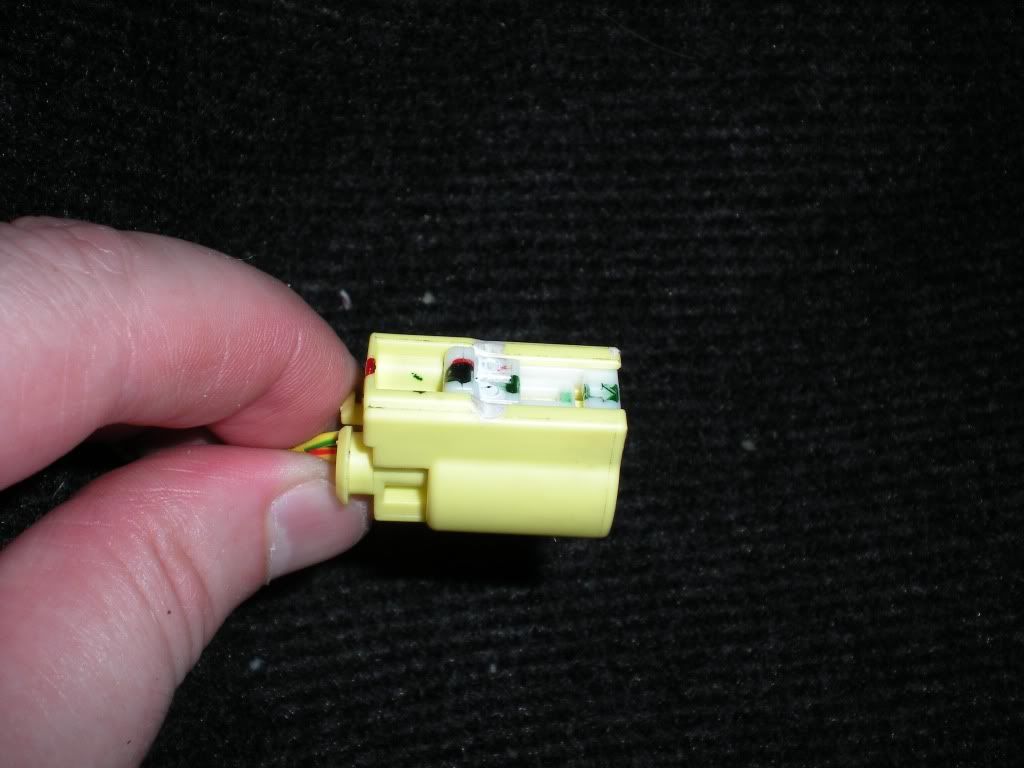
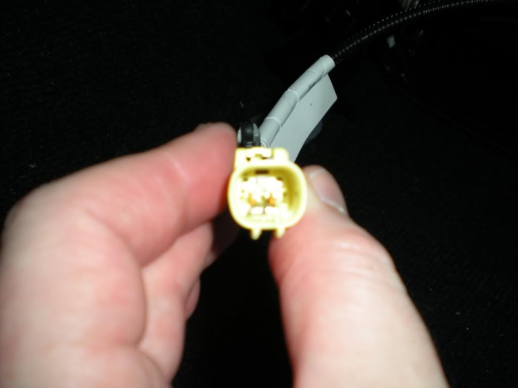
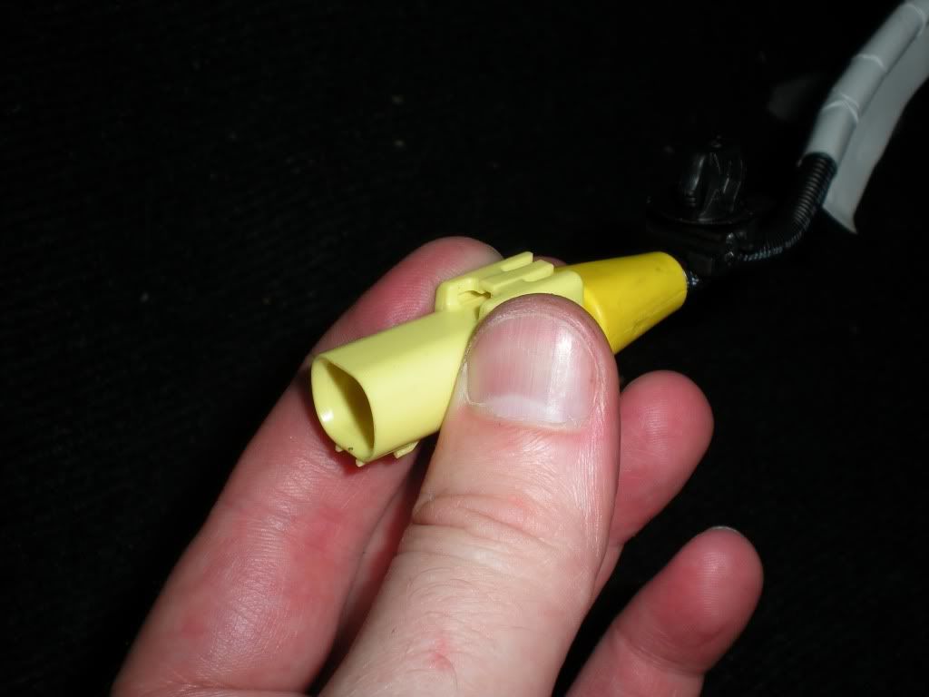
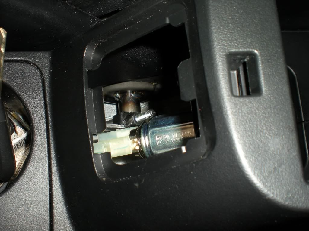
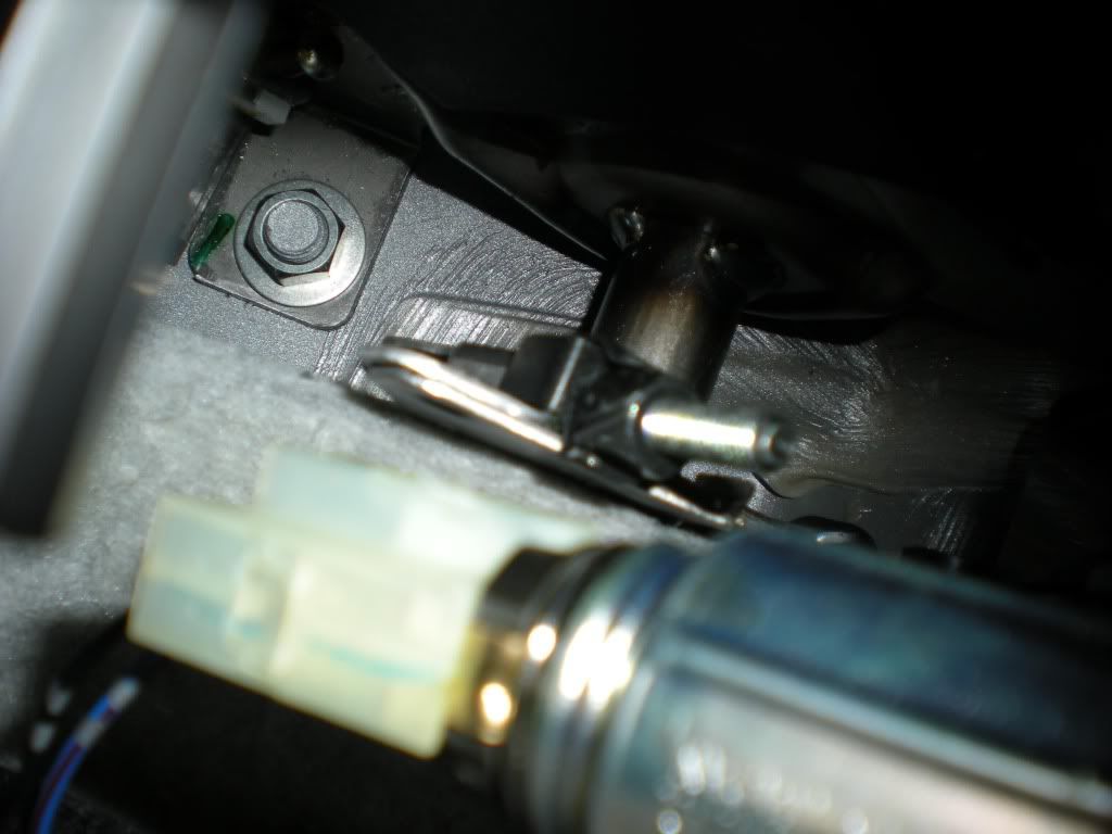
Now comes the tricky bit – underneath the seat there is a wire and a yellow plug. My guess is that is has to do with the side curtain airbag in the seat. The plug is stuck on a metal mount that is part of the seat. You need to open the plug up so you can pull the seat away. I had a lot of trouble with this. In the end I used a small screwdriver and levered the little white tab towards the rear of the truck (put in in the slot with the green colouring and push in the directions of the arrow - see pics below). Once that little thing came off I was able to disconnect the plug and pull it free of its mount. Putting the little white (locking) tab back in is hard, mainly because you first need to find the 2 tiny little springs that go in between the tab and the plug. Anyway I found this a challenge so I’m giving you a few photos of the bugger to study. It’s not life threatening or anything but I thought it a PITA at the time.
For my part I didn’t pull the seat out of the car I just tipped it back against the rear seat. This is why I suggest tilting the back of it forward before removing it from its mounts.
Now we want to remove the centre console unless you have tiny arms that can reach up into the dash from behind.
First open the console box. There are two bolts down the bottom to undo. Again I used the fancy pivoting ratchet ring spanner but that was only because I couldn’t be arsed going to find my socket set – sockets will be easier. Here’s a shot of the inside of the console box, the bolts are black.
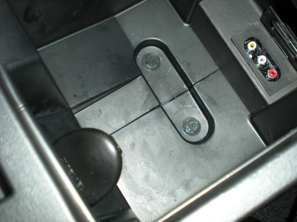
On the left side of that last shot you can see the hood on the 12V accessory outlet inside the console box. We need to fix that.
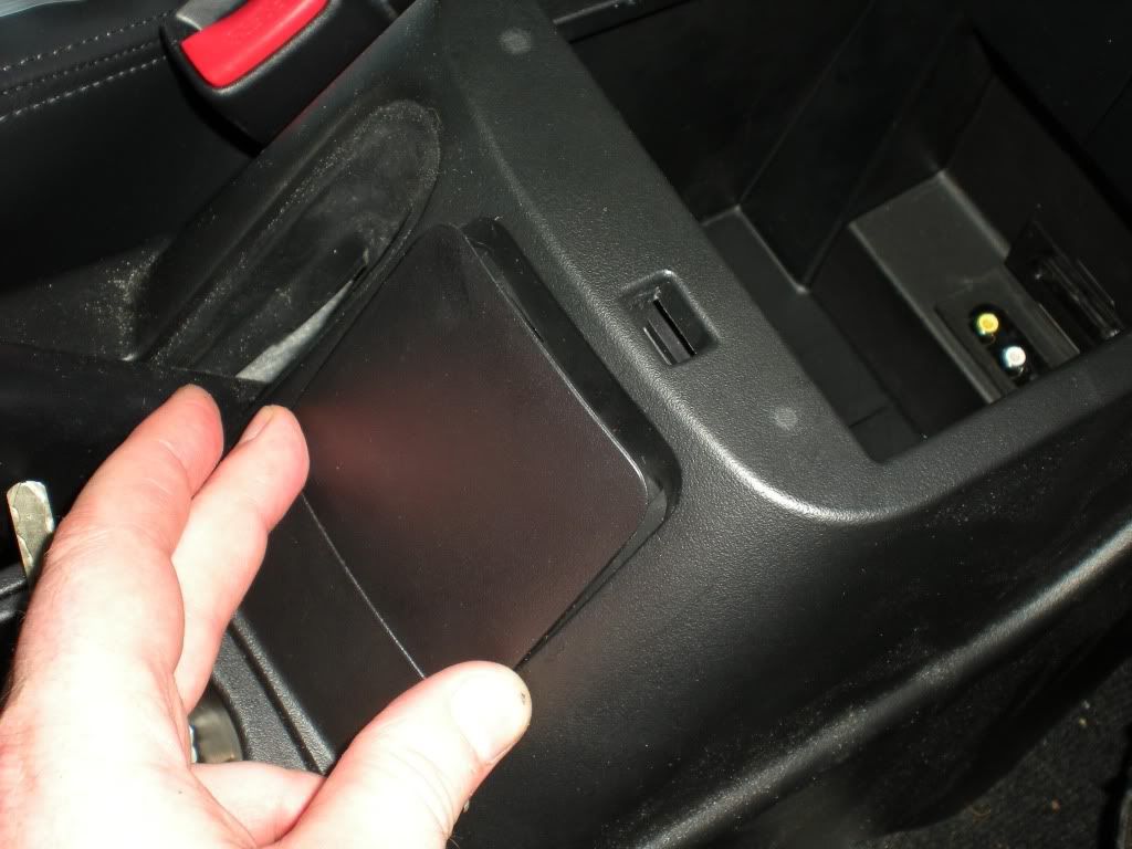
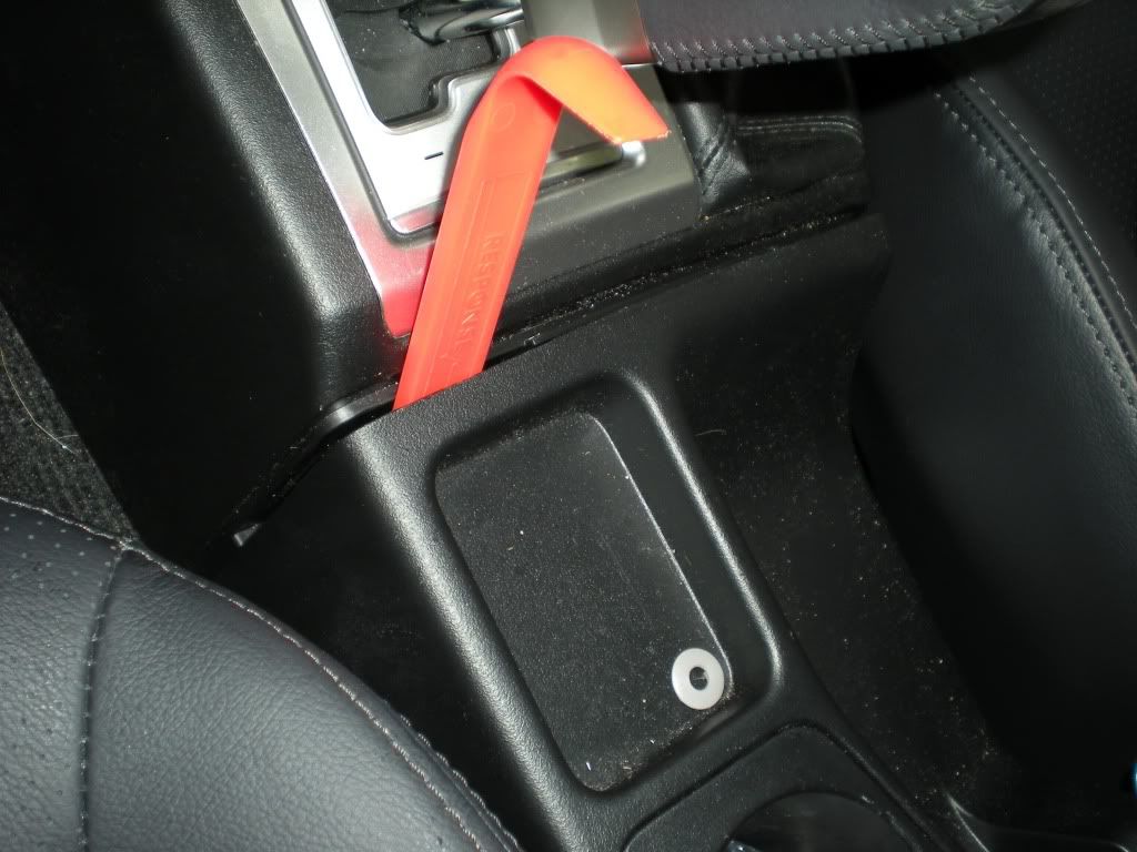
You need to remove the little plastic blanking plate on the front of the box so you can get at the wires which power the 12v accessory outlet in the console box. I think I stuck my fingers in from next to the handbrake and popped it out from there. The cable slides off the back of the plug pretty easily.
Handbrake adjustment nut in the background there somewhere (thanks Subi for that one).
The plug is on the left in this shot – push it down to the left (in the image anyway). You did disconnect the battery, right?
I didn’t take photos of the next bit and it was one of my stuff ups. At the front of the console piece which is now loose, there are two clips underneath just near where it joins the next panel. I got too brutal with one of mine and snapped it off. As best I could work out you need to pull them directly upwards to get them free. I tried levering backwards which wasn’t too clever. The console is loose enough to move it around and a have a little look under there with a torch before committing yourself. Don’t do it like this
You’ll have to wiggle it a bit to clear the handbrake. Chock the wheels if letting brake off because we might be changing gears in a minute.
Okay now for the next bit. I have an auto so it might be a tad different for those with manuals. We’re going after the shroud etc that goes around the gearsticks up to the dash. First there are 2 black scrivet clips, 1 on either side down near the carpet. They’re plastic. Push the centre in and then pull out by the outer ring. It’s a little fiddly but not hard. Now unscrew the knob on the super select lever – just turn anti-clockwise for a while.
On the auto there’s a plastic boot sort of thing on the bottom of the head on the lever. It’s silver and square with a taper at the bottom. Pull it down the shaft and it will unclip. On the driver’s side of the white nylon that will then be revealed are 2 small screws, remove both (did I mention the magnetic tray?) and then slide the head up and off the lever.
I can’t actually remember if there were any other screws etc holding this bit in. If there were you’ll see them easy enough. Lift the whole thing backwards and up and put it somewhere else.
Right now we’ve made a real mess. I went even further and pulled up the carpet and pulled off the plastic trims along the bottom of the door rails. There are reasons for this.
Before I go back to the speaker wiring, it’s time to talk power. My amp has 2x20 amp fuses in it and the amp wiring kit I bought came with a 60 amp fuse. This is not a small amount of power so I used some serious cable. It came with a kit. It’s pretty and red with nice copper showing through. Also allegedly oxygen free and stuff. So, where to run the wire? Well I’d been through the grommet behind the glovebox once before so I thought I’d give the one under the passenger seat a go. It was no easier. Both of these have tight rubber boots and you’re working in confined spaces a little. Here’s some shots.
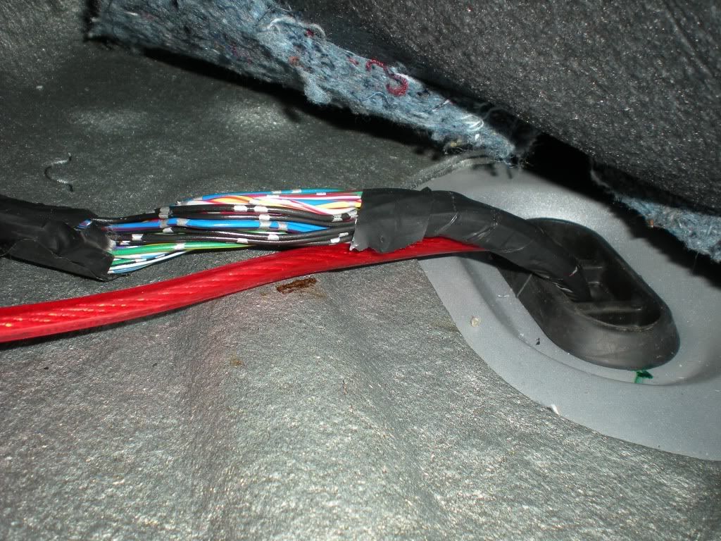
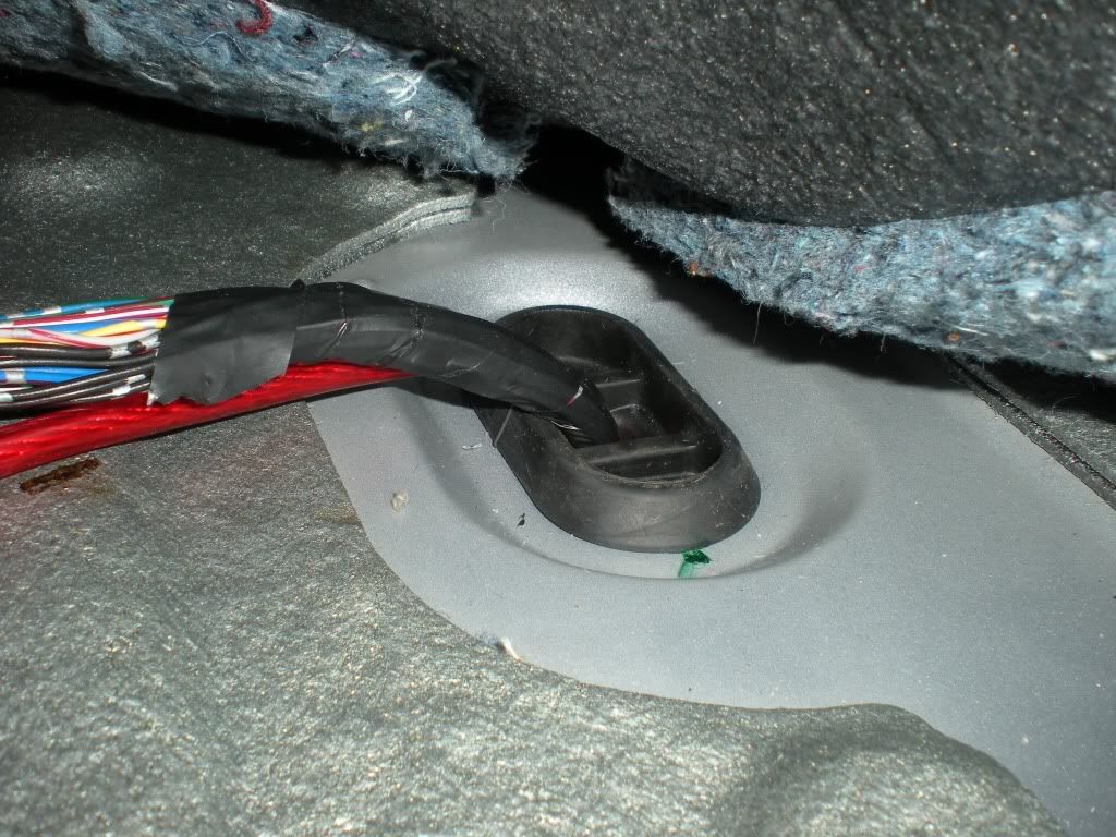
The grommet is quite big and has a sort of a snout on it at the bottom. I call it a boot but query if that’s the right terminology. The wiring coming out of it is all taped up neatly with black tape. You need to cut the tape. Use scissors or snips rather than a blade as you’ll risk nicking one of the other wires. Once all the tape is gone I used a wire coathanger doubled over into a loop to push through the grommet/boot and to pull a thin wire through. I then used the thin wire to pull through the end of my fat red wire as shown above. Leave yourself a bit spare up top for routing later.
Back underneath the truck you should now be replacing that neat black tape. The smaller your roll of tape the easier this will be and the neater you will do it. I got it looking just like factory except for the flash of red. Now would be a good time to run your wire into that split loom stuff I mentioned at the start. This stuff sucks. Maybe you could even put some of it on before the previous threading step above. I did it the hard way, upside down under the truck.
Now follow the other loom runs from this grommet down the passenger side chassis rail and up the firewall near the manual fuel pump and ASC modules (it is ASC right? Can’t remember now and it’s raining out so I’m not going to check).
I didn’t take any pictures of this but I mounted a 40 amp self resetting circuit breaker next to the battery. I crimped a ring on the end of my fat wire and put that on one side of the breaker. I used another bit of the same wire with a ring either end of it to feed the 12V+ straight off the battery to the other side of the breaker. Fuses work just as well but I’m lazy and didn’t like the idea of having to carry more spare fuses around.
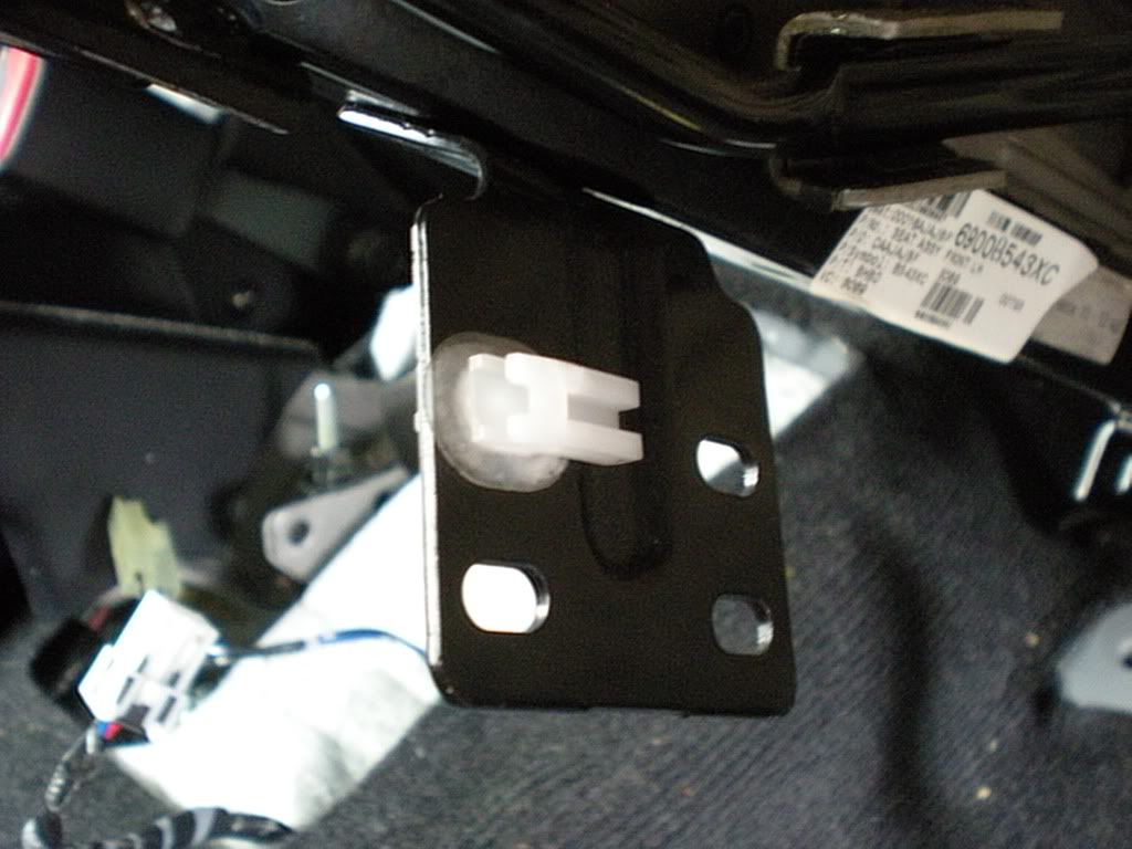
Now, back inside the car we need a good 12V earth. Again I used nice fat wire from my kit with a ring already crimped to the end of it. There is a good earth point already bolted to the body on a rib just in front of the seat well. Here’s what it looks like before my earth was added to the pile:
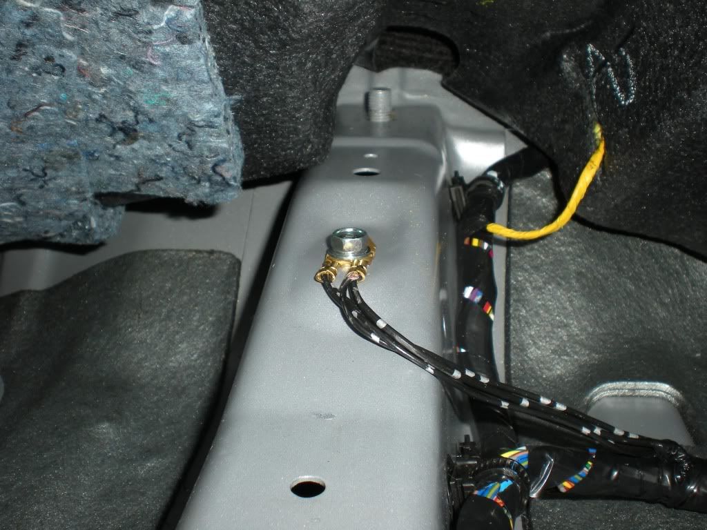
There is a hole in the carpet near this rib. The airbag seat wire we disconnected before came through this hole. I used it for my wires too.
Right, now back to the Franken-Harness. I used one of those flexible tools with the claws on the end. They’re 2-3 feet long and like a big flexible spring sort of thing. I pushed it straight down the hole at the back of the MMCS and I could then feel it at the bottom inside the dash behind the 12V accessory outlet. I tied a loop in a thin piece of wire and grabbed it with the claw. Then I pulled it through to the top to use as a cable puller.
Back down the bottom end I attached it to my speaker wires which I doubled over and cable tied in attempt to get a nice smooth front profile to aid in pulling through:
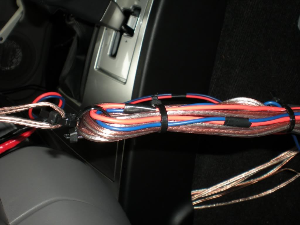
This is the one with the cable ties protecting the soldered joints:
As you can see in the second shot above the wires are now at the top of the dash. Now here’s a couple of tips based on errors I made. 1 – don’t sleeve your wires with loom or whatever before passing them through the dash, they’ll get all jammed up and it’s not worth the grief. 2 - don’t just leave them hanging up the top and start sleeving down the bottom. If you do they might fall back down into the dash
I ran some cable tidying stuff around and around the wires down the bottom to keep it all neat:

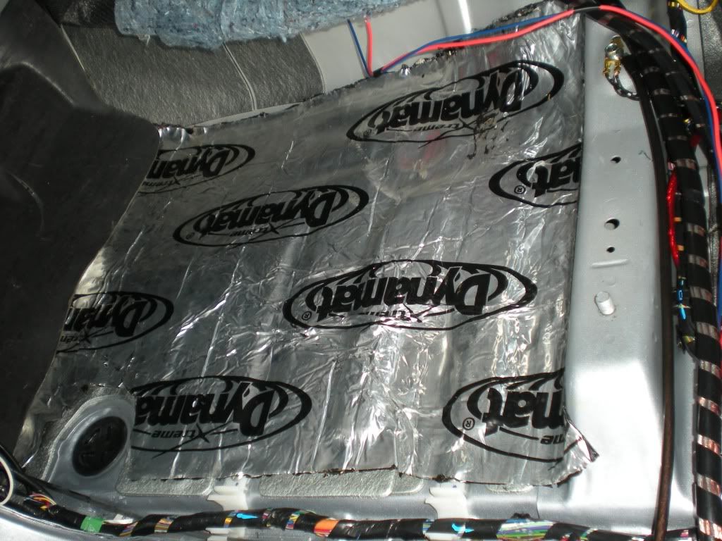
Since I had the carpet up and some dynamat left over I lined the floor of the foot well and the area under the seat. Here’s a tip though, if your amp is taller than mine don’t line under the seat, things get a little snug under there and I almost had a clearance problem I couldn’t overcome. Almost…
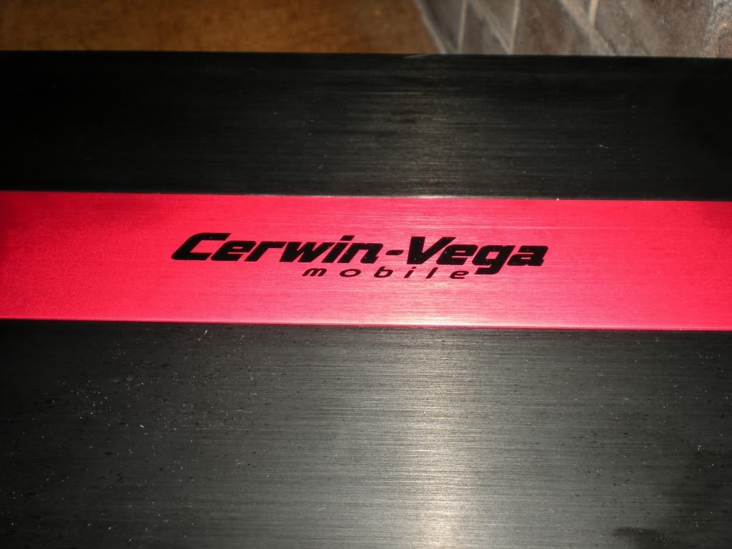
Here’s some gratuitous shots of the amp. It has a red stripe so it goes faster:
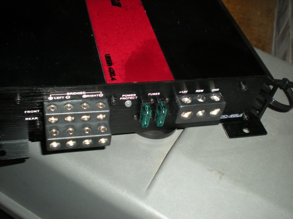
Power in, speaker outs and 2x20amp blade fuses:
Inputs and adjustable gain etc:
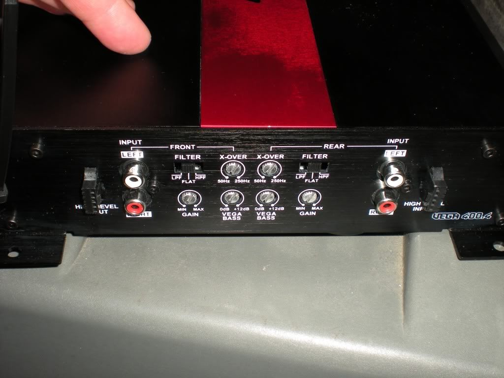
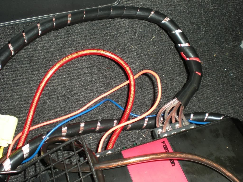
Wiring the amp (that brownie grey fat wire is the ground cable):
I was going to run my wires along under the console down the centre hump but I ended up going along the floor under the carpet right along the right hand edge of the foot well. I figured the bundle or wires was going to be too big to exit the console neatly beside the seat. This way they’re pretty much invisible unless you get under the seat.
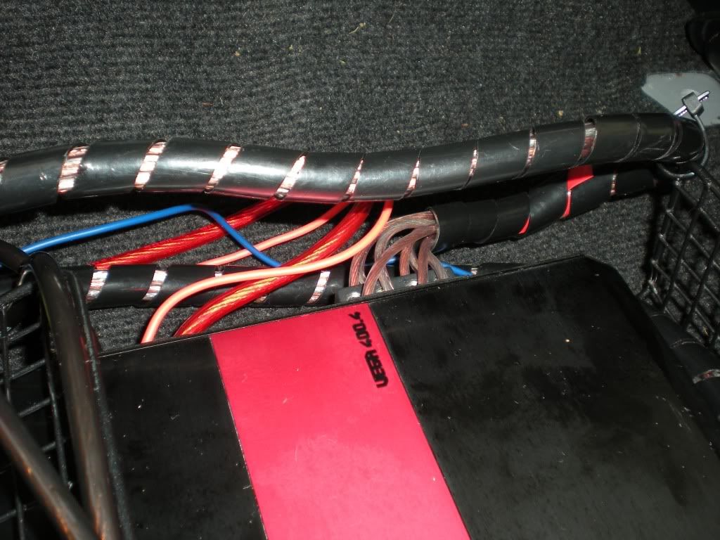
In case you’re wondering what that wire grid near the amp is I confess that I made a kind of protective cage for the amp. I used a wire baking rack I picked up at spotlight. It has little feet to keep it off the carpet a little. The amp is cable tied to it with little rubber stand offs sandwiched between the wire and the base of the amp’s feet. I shaped the rack so that it curves up and over the amp at the front and forms a vertical barrier at the back. This way nothing which goes under the seat can hit the amp but it can still breathe for cooling purposes. It’s not the best method in the world but the amp is wedged in tight and nice and protected. The excess cable is also nicely tied down to the tray so it can’t pull on the terminals of the amp. It’s not the prettiest effort but it serves the purpose I needed and it’s sort of discreet being black and all.
You may do better placing your amp lengthwise rather than cross ways as I’ve done it, there’s probably more room to do it that way.
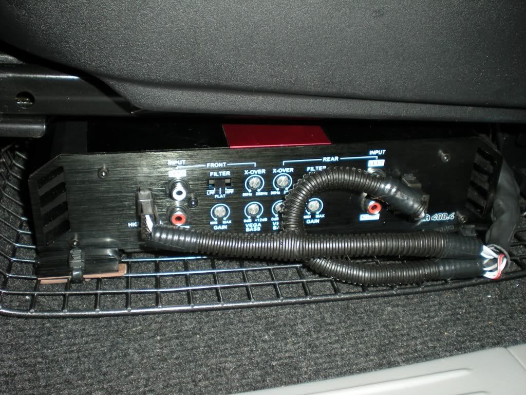
At some later stage I plan to make a Perspex cover or something for the exposed edge that sticks out of the seat in the shots above. It needs to be where you can get at it so you can adjust the gain etc (those little screws you can see on the face of the amp).
So, the wiring is through the carpet hole, the amp all connected, the carpet laid back down and it’s time to go back to the MMCS. We grab the KRAM harness that we’ve modified and the joys of plug and play come to the fore. We connect 3 iso plugs, one for speaker outs from the MMCS (in for the amp) and one for speaker outs from the amp (in for the car’s harness).
I should have put these up the top but this is what the ISO plugs look like;
Then we plug the two 20 pin connectors together between the KRAM and the vehicle harness. Now would be a good time to tidy up your wires behind the MMCS because it might be a tight fit. I did a poor job of this and will have to go back and fix it later. You should be able to push the ISO plugs back down into the square hole where you ran the wires. The 20 pin connector can sort of squeeze down in the back right corner but you’ll do that after connecting the MMCS. It’s now that the unclipping of the wires from the mount under the GPS antenna is worthwhile.
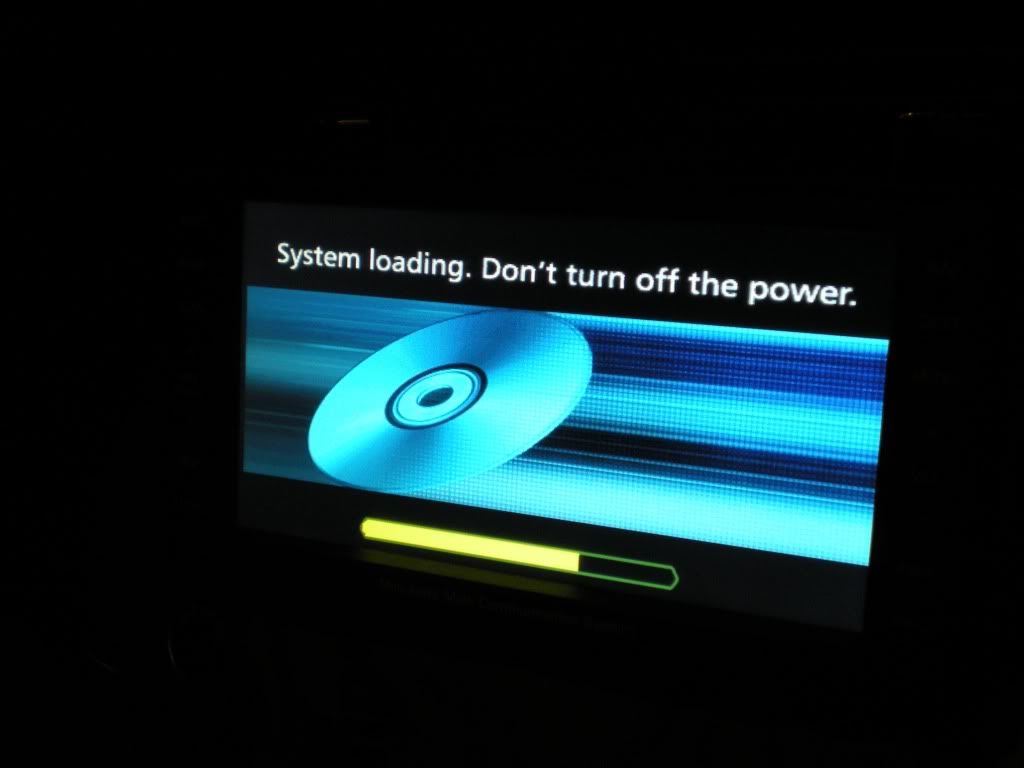
Grab the MMCS. Connect the wires back into it, starting at the bottom and working from driver’s side to passenger side (assuming you’re over on the passenger side). Note that the antenna is a tight fit and needs some force to go all the way in. Now you’ve still got that rag under the MMCS right? The cables should hold it there nicely while you go and reconnect your battery.
Turn on the ignition to accessories. If you’ve got it right it should look like this:
Now go over to this thread:
http://www.newtriton.net/phpbb/viewtopic.php?f=21&t=4480&p=66832&hilit=taming+the+mmcs#p66812
and use what’s there to go into the secret menus. Find the speaker test button and ask it to send though test tones. If you get sound in each speaker in the right place then you haven’t stuffed it up. Turn off the ignition and go to work putting everything back together again.
I took more photos during the install than I used here. I’ve put them all up as an album on photobucket if anyone is interested in the whole lot:
http://s915.photobucket.com/albums/ac360/CowboyDave_bucket/Amplifier%20installation%20shots/
After I’d done all of that I found out about the spdif 5.1 and got better info about the pin-outs. I haven’t looked at that stuff to see if I could have done it much better but there is probably a Mitsubishi genuine part that is designed to connect the MMCS to a Rockford Fosgate amp in maybe a Pajero or a Lancer. This might prove easier. Or not.
How does it sound? Great, even if I do say so myself.
That may well be the longest post ever. Hopefully it's of some use to those who come after me.


